©Copyright Task Force Tips, LLC 2002 - 2018 LIA-200 March 20, 2018 Rev19
4
3.0 GENERAL INFORMATION
NOTICE
Ball intake valves were initially designed as Large Diameter Hose intake valves. Ball Intake Valves
function as either a pressure (discharge) or vacuum (intake) valve for Large Diameter Hose. The
manual applies to both applications of Ball Intake Valves.
The Ball Intake Valve and the Jumbo Ball Intake Valve are intended for use on the intake manifold of a re engine. The valve is kept
closed while the water supply from a hydrant or another pumper to the engine is being established. This prevents the pump from
sucking air through the intake manifold and losing its prime. Once the supply hose is lled and under pressure, and the air has been
vented from the hose, the valve may be opened to connect the pump to the water supply. An adjustable pressure relief valve mounted
on the bottom of the valve opens to relieve any excess pressure that may damage the hose or the pump.
An electric remote controlled (RC) model allows the valve to be operated from a remote location. A typical installation will consist
of the BIV RC and a remote display operator station. Motor controls are designed to auto sense 12 VDC or 24 VDC operation. The
motor control circuit utilizes a position encoder and current limiting to protect the drive train at the ends of travel. Unit is supplied with
2’ of cable with a plug on BIV RC and 10’ of cable with a receptacle so installation eort is minimized. Cable has only four conductors
(two for power and two for communications) further easing installation eort. To complete the installation, the installer will need to
mount and wire the remote display operator station. The power supply for the BIV RC will need to be connected to a protected circuit
from the trucks power distribution center. Refer to the specications section 3.1 for nominal current draw.
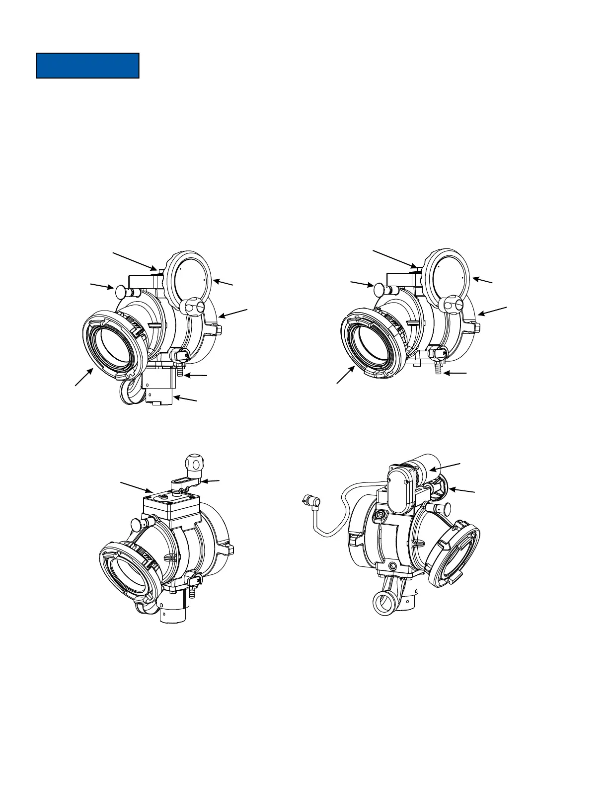
Intake
Elbow
Swivel
Side B
Coupling
Air Vent & Drain
Outlet
Side A
Handwheel
Shot Pin
Knob
Air Vent
& Drain
Handwheel
Intake
Elbow
Swivel
Side B
Coupling
Shot Pin
Knob
Outlet
Side A
AB1ST-NX
Ball Intake Valve w/Pressure Relief Valve
AC1ST-NX
Ball Intake Valve
Valve Pointer
Location
Crank
Hand Wheel
Electric Motor
PLUG
AB1ST-NX-PS
Ball Intake Valve With Parallel Drive Gearbox
AB1ST-NX-RC
Ball Intake Valve RC