L1
L2
L3
L4
L5
L6+L7
L7
L8
red
red
green
green
green
green/
red
green
red
Indicates the pedestrian command is working.
Indicates the step-by-step command is working.
Indicates the stop command is working.
Indicates the photocell input is working.
Indicates the fixed edge device is working.
Indicates the presence of 12Vac in the card.
Indicates the presence of battery powered 12Vdc in the card.
Indicates the presence of 220/230 V mains power at terminals 32-33.
DIP-SWITCH A
N° 1
N°2
N°3
N°4
N°5 - 6
OPEN/CLOSE PUSH BUTTON WITH STOP ON stop enabled.
With this dip switch OFF the open/close push button functions as described in the point dip switch
n.3A. With the dip switch ON, by pressing the open/close push button we will have the following
phases: OPEN - STOP - CLOSE - STOP - OPEN etc.
PHOTO DEVICE IN THE OPENING PHASE ON also enabled in opening.
With this dip switch OFF the photo device functions only in the CLOSING phase, it stops for about 2
seconds and then causes an OPENING phase.
With the dip switch ON the photo device also functions in the OPENING phase; the gate will stay still
until the obstacle interrupts the photo device’s beam; the gate will open when reset.
OPEN/CLOSE PUSH BUTTON IN THE OPENING PHASE ON also enabled in opening.
With this dip switch OFF by pressing the open/close push button direction will be reversed only in the
CLOSING phase. With the dip switch ON the open/close push button will ALSO reverse the direction
in the OPENING phase.
AUTOMATIC RECLOSING ON enabled.
With this dip switch OFF, once the gate is open, it will only close again if a manual command is given.
With the dip switch ON, once the gate is open, it will CLOSE AGAIN AUTOMATICALLY after a set
programmed PAUSE time.
SLOWING DOWN 4 Levels.
By slowing down we mean when the gate reaches the end of its travel and the motor is supplied with a
lower voltage. The length of time of this phase is proportional to the pulses detected by the encoder
in the memorization manoeuvre. For the automation of bars we suggest a 50% deceleration.
DIP SWITCH PROGRAMMING
DIP n° 5
OFF
OFF
ON
ON
DIP n° 6
OFF
ON
OFF
ON
%
4.68
12.5
37.5
50
EXAMPLE with 100 memorized pulses:
95.32 pulses at normal speed, 4.68 pulses at a reduced speed
87.5 pulses at normal speed, 12.5 pulses at a reduced speed
62.5 pulses at normal speed, 37.5 pulses at a reduced speed
50 pulses at normal speed, 50 pulses at a reduced speed
pag.18
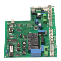
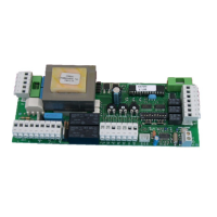
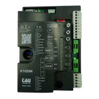
These control panels are fitted with several indicator LEDs that can help during the final testing phase, (if N.C.
inputs are not used it is necessary to connect them to the common). The small green LED’s indicate N.C.
inputs, if the contacts are closed the LED’s must be on (if N.C. inputs are not used, they must be connected to
the common conductor).
FINAL TEST OF THE SYSTEM