16
Systems and Controls
Models 340/341/342
Component Replacement
Note: DO NOT attempt any repairs unless
the MAIN POWER SUPPLY TO THE FREEZER HAS
BEEN DISCONNECTED. Failure to follow this
instruction may result in electrocution.
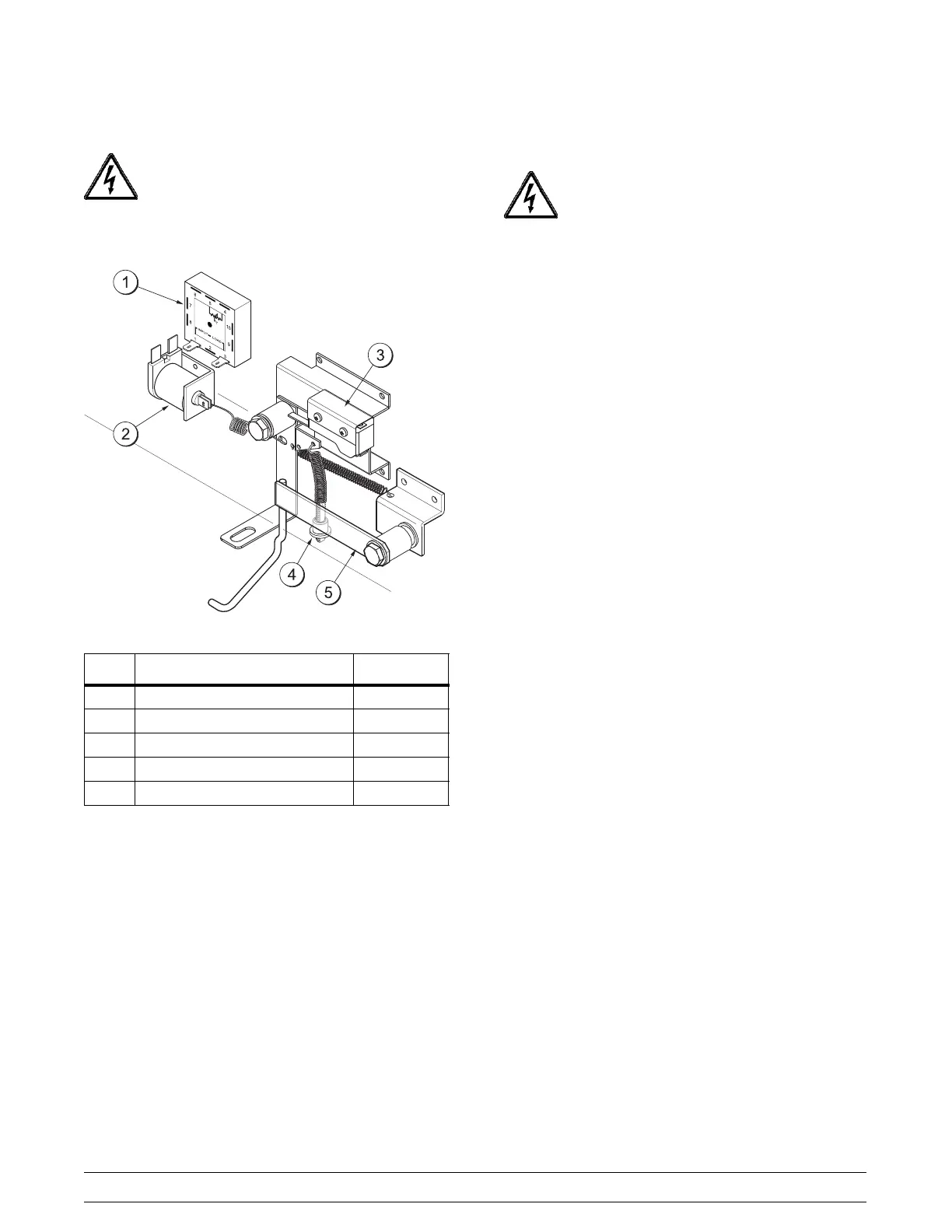
Figure 2
ITEM DESCRIPTION PART NO.
1 Timer 029312--12
2 Solenoid 030202--12
3 Microswitch 027026
4 Adjustment Knob 014499
5 Mechanical Anticipator Arm X29556
If the timer, microswitch, toggle switch or solenoid is
faulty, simply replace by:
Note: DO NOT attempt any repairs unless
the MAIN POWER SUPPLY TO THE FREEZER HAS
BEEN DISCONNECTED. Failure to follow this
instruction may result in electrocution.
Step 1
Remove the front switch cover assembly.
Step 2
Disconnect the wires to the particular component.
Step 3
Remove the mounting screws and pull the component
out.
Step 4
Install the new component, following the reverse
procedure of the above steps.
Step 5
Check for proper adjustment and operation of the
component.

 Loading...