56
Systems, Controls and Operations
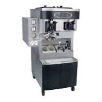
Model C602
Spinner Mot o r Bracket
The actuator plate should ride gently against the
rear guide post.
The guide post is mounted underneath the spinner
motor bracket. (See Figure 100.) Moving the bracket
forward brings the guide post forward.
IMPORTANT: When properly aligned, the
actuator must move freely without any tension
on the guide post.
Figure 100
To adjust the alignment, perform the following
steps:
Step 1
Loosen the four hex head screws that secure the
spinner motor bracket to the control channel
bracket.
Step 2
Slide the bracket forward or backward to the correct
position and secure the four screws.
Solenoid Valve
The solenoid valve should be vertically aligned so
the plunger moves freely in the coil without side
load. The height of the solenoid should be adjusted
to raise the draw valve to the top of the product port
in the freezer door.
With the spinner blade and the driven spinner
removed, and the draw valve in the raised position,
look inside the freezer door. The bottom of the draw
valve should be located at the top of the product
entry port.
If the valve is too high or too low, the height of the
solenoid will need adjustment.
To adjust the solenoid height, use the Solenoid
Adjust Tool Kit Assembly (X59702) and perform
the following steps:
Step 1
Place the power switch to the OFF position and
disconnect power to the machine.
Make sure the power switch is in the
OFF position. Failure to follow this instruction may
result in severe personal injury from hazardous
moving parts.
Step 2
Remove the front control panel.
Step 3
Loosen the two 7/16” nuts that secure the draw
solenoid to the mounting bracket. The solenoid
spring tension will push the coil to the top of the
adjustment slots in the bracket.
Step 4
Remove the restrictor cap, spinner blade, and the
driven spinner from the shake door.
Step 5
Rinse the area below the draw valve.
Step 6
Lubricate the two o-rings and install the Solenoid
Adjust Tool into the door spout. Lift the draw valve to
insert the tool into the door. Install the restrictor cap
to retain the tool with the draw valve in the raised
position. (See Figure 101.)
Figure 101