5
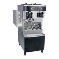
Model C602
Introduction
Installation Instructions
Thismachinemustbeplacedonalevel
surface. Failure to comply may result in personal
injury or equipment damage.
DO NOT installthemachineinanarea
where a water jet could be used to clean or rinse the
freezer. Failure to follow this instruction may result in
serious electrical shock.
Disconnect Switch
Stationary appliances which are not
equipped with a power cord and a plug or other
device to disconnect the appliance from the power
source must have an all-pole disconnecting device
with a contact gap of at least 3 mm installed in the
external installation.
Air Cooled Units
These units require a minimum of 3” (76 mm) of air
clearance around all sides. Install the deflector
provided to prevent recirculation of warm air.
Minimum air clearances must be met to assure
adequate air flow for optimum performance.
Gear Alignment and Rear Shell Bearing
1. Make certain the drive shaft can easily slide in
and out of the female socket on the gear unit.
2. If a drive shaft is binding, the gear unit could be
out of alignment (loose). Check the bolts on the
gear unit to be sure they are tight.
3. Inspect the rear shell bearing for tightness. Be
sure the locking tab has been folded over to
prevent the nut from loosening.
Note: If the gear unit is out of alignment, refer to
the General Service Manual.
Beater Rotation
REMEMBER TO DISCONNECT ALL
POWER TO THE FREEZER! Failure to follow this
instruction may result in electrocution.
Beater rotation = CLOCKWISE (when viewed from
the front of the machine).
Note: This machine is equipped with an interlock
circuit that prevents beater motor operation when
the freezer door is not installed.
1. Remove the side panels.
2. Place the power switch in the ON position.
3. Select the WASH key on the control panel. This
activates the beater motor only.
CAUTION: Hazardous moving
components! Keep your hands clear when
operating the machine with the panels
removed. Failure to follow this instruction may
result in severe personal injury from hazardous
moving parts.
4. Check the rotation of the drive coupling located
on the output shaft of the gear reducer. The
coupling should be turning CLOCKWISE as
viewed from the front of the machine.
5. Press the WASH key again to stop the beater
motor.
If rotation is not correct, exchange any two incoming
power lines at the freezer main terminal box only
(splice box).
REMEMBER TO DISCONNECT ALL
POWER TO THE FREEZER! Failure to follow this
instruction may result in electrocution.