6-6
OPERATING PROCEDURES
Model C706
Operating Procedures
6
Note: The drive hole in the mix inlet adapter must be
visible through the drive hole opening in the pump
cylinder, and the aligning notch located at the base of the
adapter must be positioned in the notch at the bottom of
the pump cylinder.
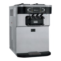
9. Secure the pump parts in position by sliding the
retaining pin through the cross holes at the bottom of
the pump cylinder.
Figure 6-21
Note: The head of the retaining pin should be facing
up with the pump correctly installed.
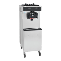
10. Assemble the feed tube assembly. Slide the valve
O-ring into the groove of the feed tube.
Figure 6-22
11. Install one red O-ring on each end of the mix feed
tube and thoroughly lubricate.
Figure 6-23
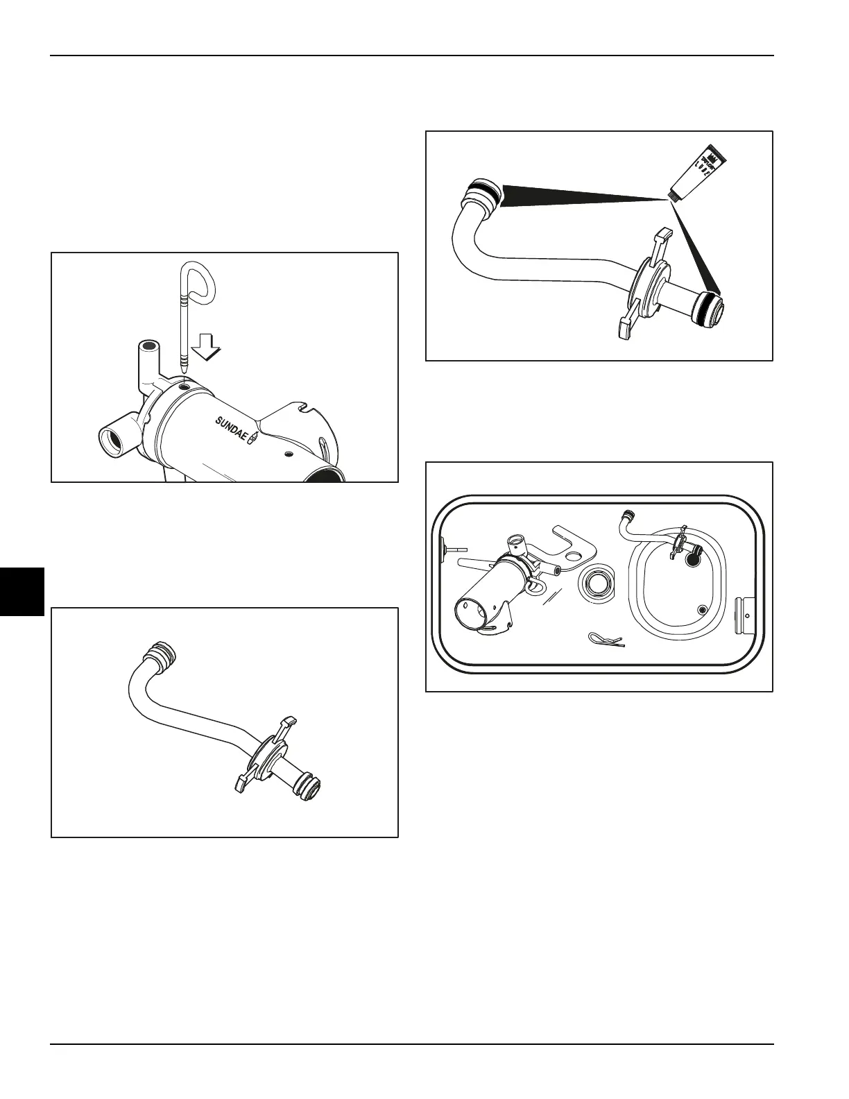
12. Lay the pump assembly, pump clip, mix feed tube,
and cotter pin in the bottom of the mix hopper for
sanitizing.
Figure 6-24

 Loading...