16
Model C707Operating Procedures
140618
Step 4
Install the draw valve. Slide the two o- rings into the
grooves on the draw valve, and lubricate.
Figure 12
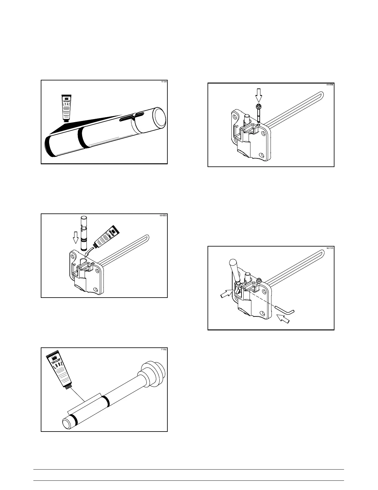
Lubricate the inside of the freezer door spout, top and
bottom, and insert the draw valve from the top until the
draw valve is at the bottom.
Figure 13
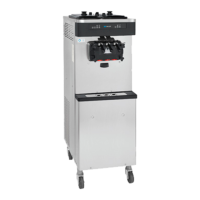
Slide the two o- rings into the grooves on the prime
plug. Apply an even coat of Taylor Lube to the o- rings
and shaft.
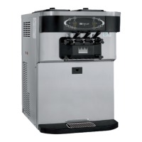
Figure 14
Insert the prime plug into the hole in the top of the
freezer door, and push down.
Figure 15
Step 5
Install the adjustable draw handle. Slide the fork over
the bar in the slot of the draw valve. Secure with pivot
pin.
Figure 16
Note: This unit features an adjustable draw handle to
provide the best portion control. The draw handle can
be adjusted for different flow rates. See page 12 for
more information on adjusting this handle.
Step 6
Install the freezer door. Insert the baffle rod through
the opening in the beater and seat the door flush with
the freezing cylinder . With the door seated on the
freezer studs, install the handscrews. Tighten equally
in a crisscross pattern to insure the door is snug.