______________________________________________________________________________________________________________________________________________________________________________
____________________
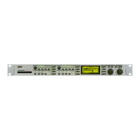
Signals to and from the LCD comes directly from the Bus Interface on the CPU board. IC1 make a 8x8 matrix which actives all the LEDs and 7-segments. IC2+3 make a 8x4 matrix which scannes all the
keys and encoders.
Front board for M5000X:
The board has only one dual color LED and two resistors. See section LED error codes for decoding the LED color.
Software Changes:
Software changes from version 1.15 to 2.00:
Please refer to service note no. 712 10 05 12 in appendix.
 Loading...
