MFC Kit Instructions 3.0 Pre-Installation Planning
8
Table 1: MFC Sine Wave Filter Technical Specifications
Intermittent overload current of 150% for 1 minute / hour
480 V and 600 V, 3-phase, at fundamental base frequency configured to Volts
per Hz
Maximum peak voltage of output waveform
480 V models: 815 V
600 V models: 1,018 V
Maximum dV/dt of output waveform
480 V models: 5 V/μs
600 V models: 6 V/μs
6,600 ft (2,000 m), derating required for operation above this level
-30°C (-22°F) to 50°C (122°F)
Cooling provisions required for operation above this temperature.
-40°C (-40°F) to 50°C (122°F)
Reference Technical Standards
3% at nominal voltage, frequency and rated current
High endurance design (no PCBs)
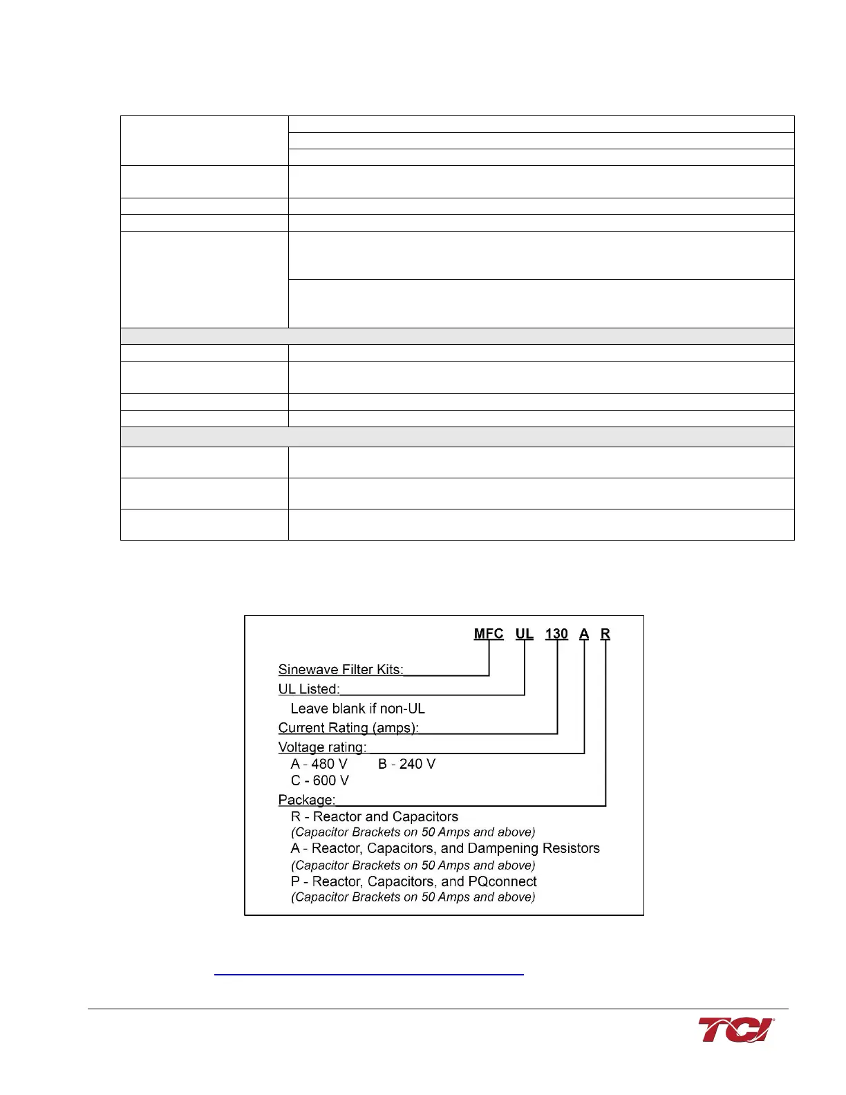
Part Number Encoding
The figure below indicates the significance of each character in the MFC part number. The example
part number MFC130AR designates an MFC kit that is rated 130A, 480 Volts and does not include
resistors.
Figure 1: MFC Kit Part Number Encoding
NOTE: Individual part drawings for each component included in the MFC Filter Kits are found at:
https://transcoil.com/products-kmg-mfcdrawings-htm/