MFC Kit Instructions 5.0 PQconnect Option
31
Modbus RTU Connections
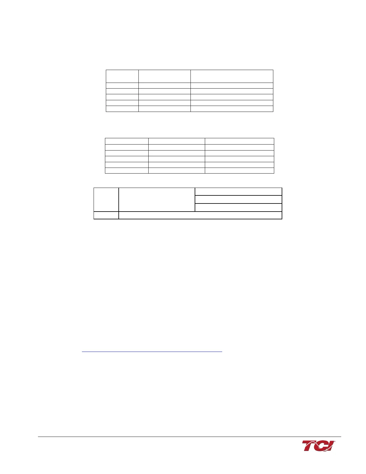
The hardware pinout for the J5 communication header and default settings is shown below.
Table 9: Modbus Connector Pin Definitions
The default protocol settings for the RS-485 Modbus RTU interface are shown below.
Table 10: Modbus RTU Protocol Settings
The input registers from the Sine wave filter are mapped to Modbus register address 40000, see
Table 20 through Table 22 for definitions of the input register maps. The output registers are
mapped to Modbus register address 40500, see Table 20 through Table 22. All input and output
registers are two bytes in size and formatted as 16-bit signed integers.
Note: All parameters with an asterisk (*) in the description will require the Tech level access codes
parameter key A: 0x007D (125) and parameter key B: 0xEA6E (60014).
PQvision PC application Screen Elements
This section focuses on the operation of the PQvision application. The PC application contains
several screens that allow the user to monitor the status of the MFC Sine Wave filter. Additionally,
the PQvision application can be used for basic setup of the MFC Sine Wave filter.
Enter password 08252014 to enable tech access.
Please ensure the latest version of PQvision is downloaded to your PC. The software is available
on the TCI MFC Kit page located here:
https://transcoil.com/products-kmg-mfcdrawings-htm/