MFC Kit Instructions 3.0 Pre-Installation Planning
16
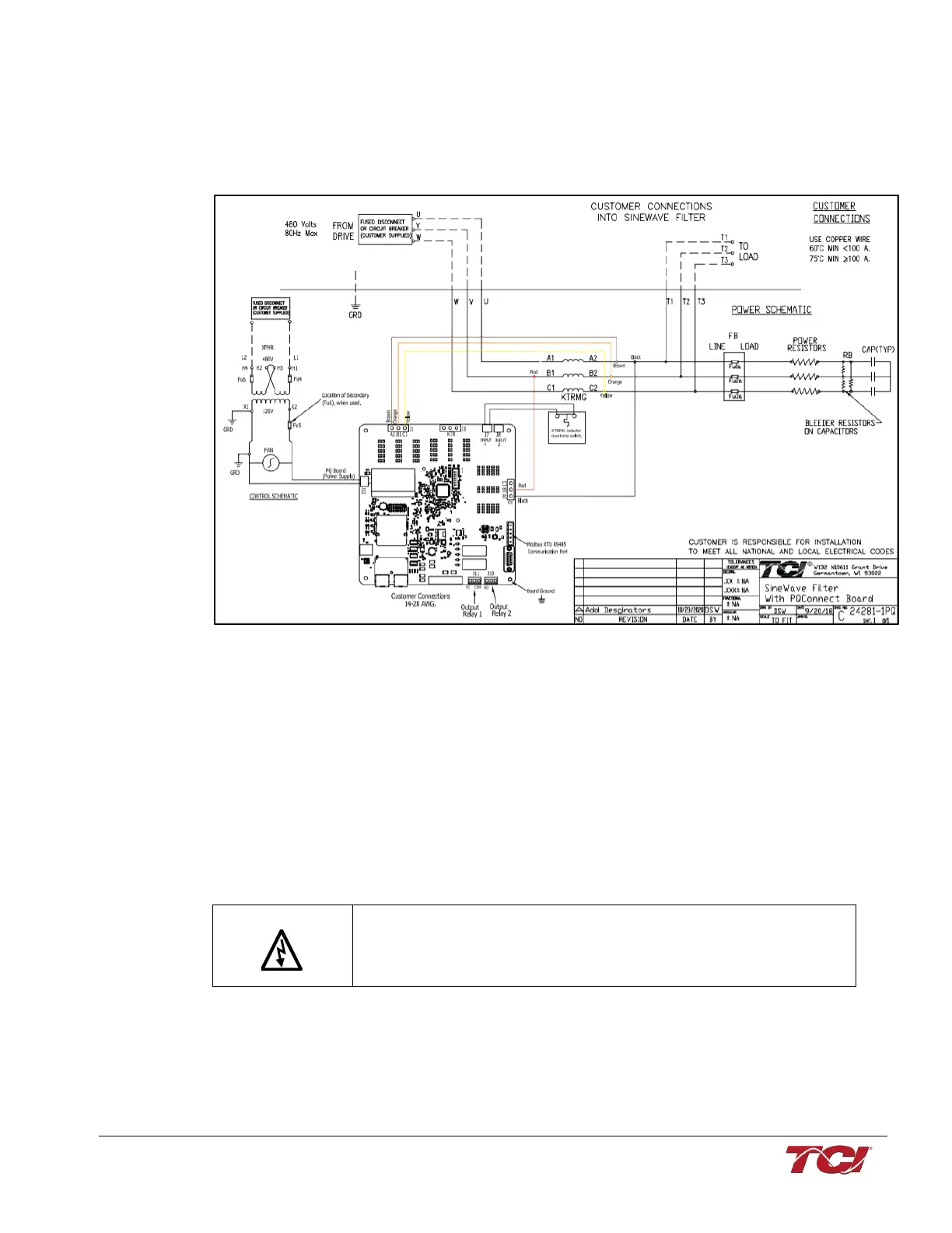
The schematic shown in the figure below is an illustration of a typical MFC kit with PQconnect (AP,
CP) filter wiring.
Figure 6: Typical MFC “P” Filter Kit Wiring
*DISCONNECT NOT REQUIRED BY UL IF FILTER SUPPLIED BY LOAD SIDE OF POWER
CONVERSION EQUIPMENT (VFD)
Capacitors
The high-endurance, PWM current ripple rated capacitors supplied in the MFC Filter kit are in
shunt with the load. In the case of the MFC “A” Filter Kit, the capacitors are wired in series with
the power resistors. If multiple capacitors are supplied with the kit, they are intended to be
connected in parallel with each other. Typically, the capacitors are three-terminal, three-phase
capacitors with the internal capacitive elements connected in delta. Each capacitor has a bleeder
resistor connected across the three input terminals to ensure voltage discharges in the time
required by UL.
Do not connect capacitors to power unless the bleeder resistors are
connected, otherwise, hazardous voltages will remain across the
capacitors after the power has been disconnected.
Kits below 50 Amps are supplied with single phase capacitors for each filter.
These capacitors are connected in wye, and the bleeder resistors are connected across the
terminals of each capacitor.