MFC Kit Instructions 3.0 Pre-Installation Planning
14
Filter Schematic
The schematic shown in the figure below is an illustration of a typical MFC filter wiring.
Figure 2: Typical MFC “A” Filter Kit Wiring
*DISCONNECT NOT REQUIRED BY UL IF FILTER SUPPLIED BY LOAD SIDE OF POWER
CONVERSION EQUIPMENT (VFD)
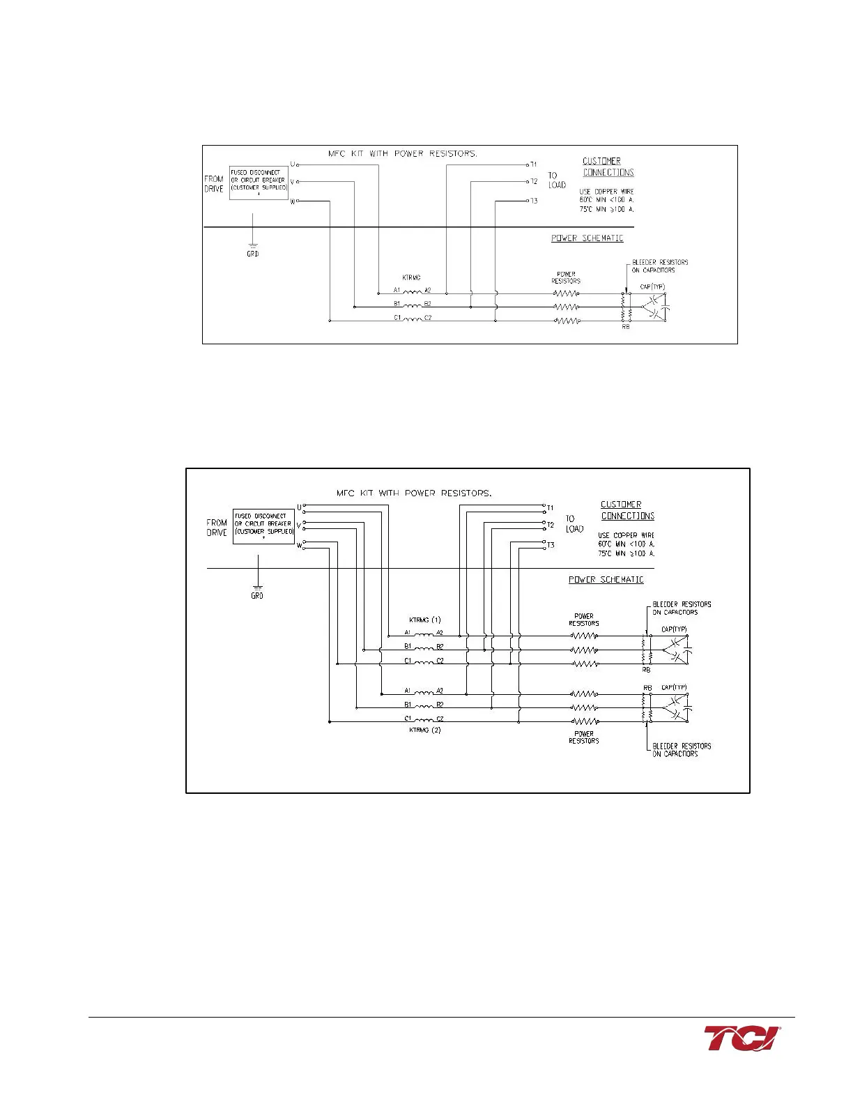
For horsepower ratings 480 V/ 900 HP and larger the series line reactor is comprised of two parallel
KTRMG reactors, as illustrated in the schematic below.
Figure 3: Typical MFC “A” Filter Kit Wiring for 480 V/900 HP and larger with two reactors
*DISCONNECT NOT REQUIRED BY UL IF FILTER SUPPLIED BY LOAD SIDE OF POWER
CONVERSION EQUIPMENT (VFD)