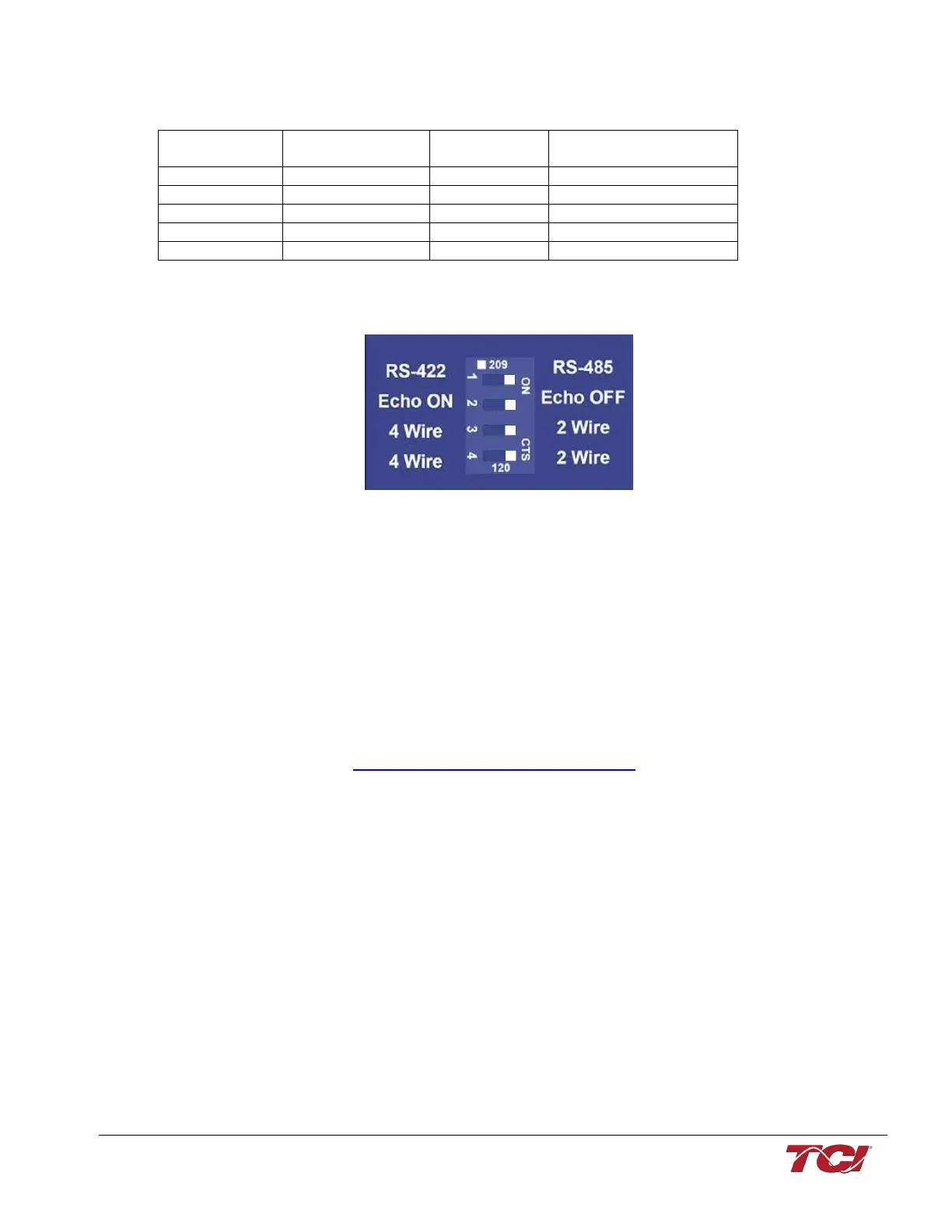
USPTL4 RS485 Converter Dip Switch settings
All four switches of the B&B converter from the factory should be set to the ON position and should
look like the following.
Figure 23: Dip Switch settings
Example Setup Instructions to Read Data from the PQconnect Unit:
• Connect the cable to the communication header on the side of the board
• Connect USB end to the computer
o Determine the assigned COM port number for the RS-485 to USB converter
using the computer device manager control panel.
o The converter used in this example typically enumerates between the range
of COM5 to COM20 on a standard laptop computer running the Microsoft
windows operating system
• Open the Simply Modbus Master software
o Can be downloaded from the link below:
o http://www.simplymodbus.ca/manual.htm
o The trial version of the software is free and fully functional for this task hence
no License key is necessary
• Next, configure the fields in the screen as shown below. These are again the default
settings of the PQconnect COM port.
o Note: The “notes” section of the display data registers are filled in manually