- 16 -
2. ELECTRICAL PARTS AND PROCEDURES FOR CHECKING
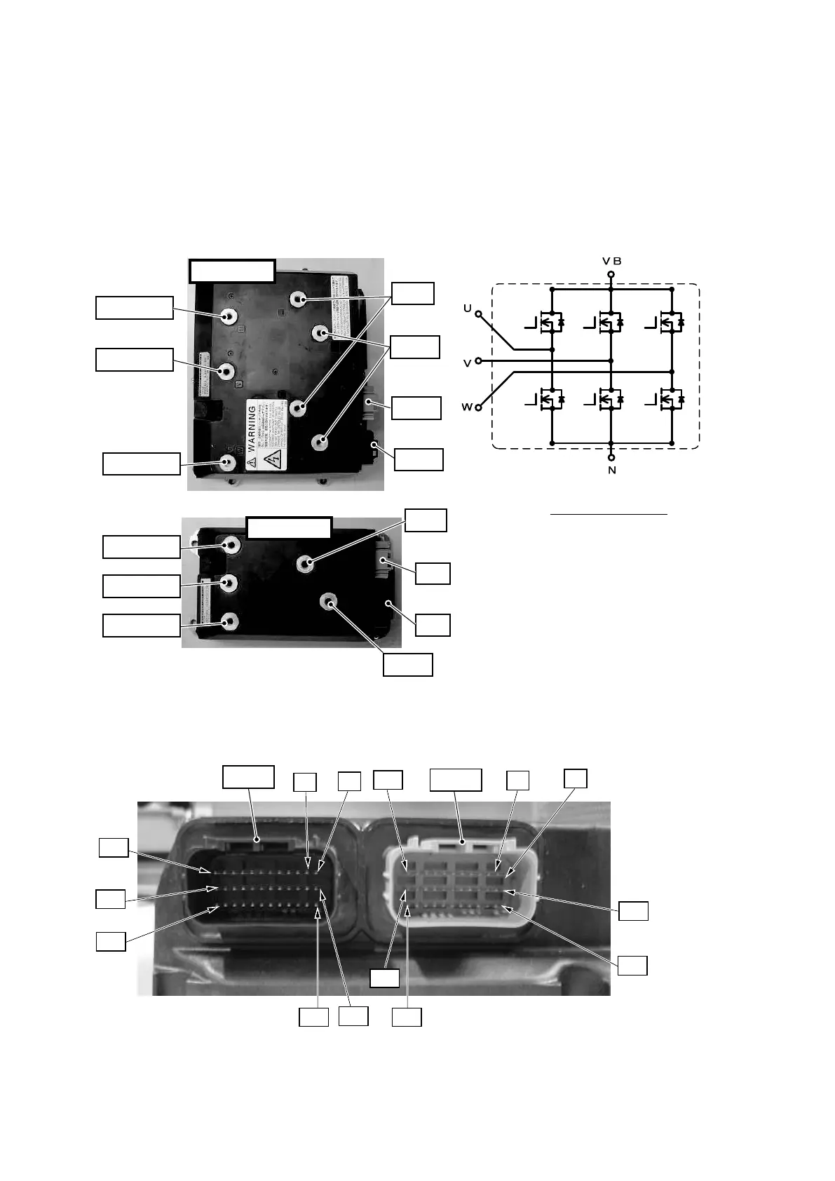
2.2.2 INVERTER UNIT
The truck has two inverter units for the drive and pump motors, each having output terminals U, V
and W to the motor and power supply terminals (+) and (-).
The pump motor inverter unit of 1-ton class trucks (excluding those with an Orbitrol steering
system) is an S-type.
1. Main circuit terminal location and internal circuit diagram
2. Connector pin numbers
CN1D. P
CN2D. P
2
1
13
25
36
24
12
2
1
12
24
36
25
13
N端子
N端子
VB端子
VB端子
CN2D.P
CN2P
CN1P
CN1D.P
U相モータ端子
U相モータ端子
V相モータ端子
V相モータ端子
W相モータ端子
W相モータ端子
Lタイプインバータ
Sタイプインバータ
内部回路図
L-type inverter
U-phase motor
terminal
V-phase motor
terminal
W-phase motor
terminal
N terminal
VB terminal
Internal circuit diagram
N terminal
VB terminal
S-type inverter
U-phase motor
terminal
V-phase motor
terminal
W-phase motor
terminal
 Loading...