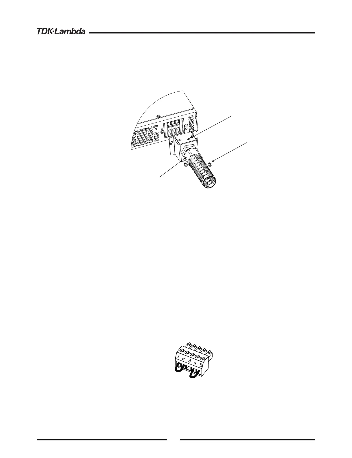
Fig.3-3: AC input cover and strain relief, 1500W models
4.Route the AC wires to the input connector terminals as required. To connect the wires, loosen
the terminal screw, insert the stripped wire into the terminal and tighten the screw securely
(4.4-5.3 Lb-inch.).
5.Route the wires inside the cover to prevent pinching. Fasten the cover to the unit using the
M3x8 Flat Head screws are provided. Strain relief cover could be opened for inspection.
Refer to Fig.3-3 for details.
3.8 TURN-ON CHECKOUT PROCEDURE
3.8.1 General
3.8.2 Prior to Operation
The following procedure ensures that the power supply is operational and may be used as a basic
incoming inspection check. Refer to Fig.4-1 and Fig.4-2 for the location of the controls indicated in
the procedure.
1. Ensure that the power supply is configured to the default setting:
-AC On/Off switch at Off position.
-Dip switch : All positions at Down (”Off”) position.
-Sense connector : Configured to Local Sense as shown in Fig.3-4:
1 Remote (+) sense
2 Local (+) sense
3 Not connected
4 Local (-) sense
5 Remote (-) sense
-For units equipped with IEEE option, ensure that the IEEE_En switch is in Up (default) position
(Refer to Fig.4-2, item 8 for location), if checkout is to be done in IEEE mode.
Fig.3-4: Sense connector default connection
Plug P/N: MC 1.5/5-ST-3.81
(Phoenix)
Removable cover.
Remove only to inspect AC input
wires connection. Reinstall cover
after inspection.
Assembled Strain Relief
M3x8
Flat Head screws
(2 places)
16