16
1.4.3.2
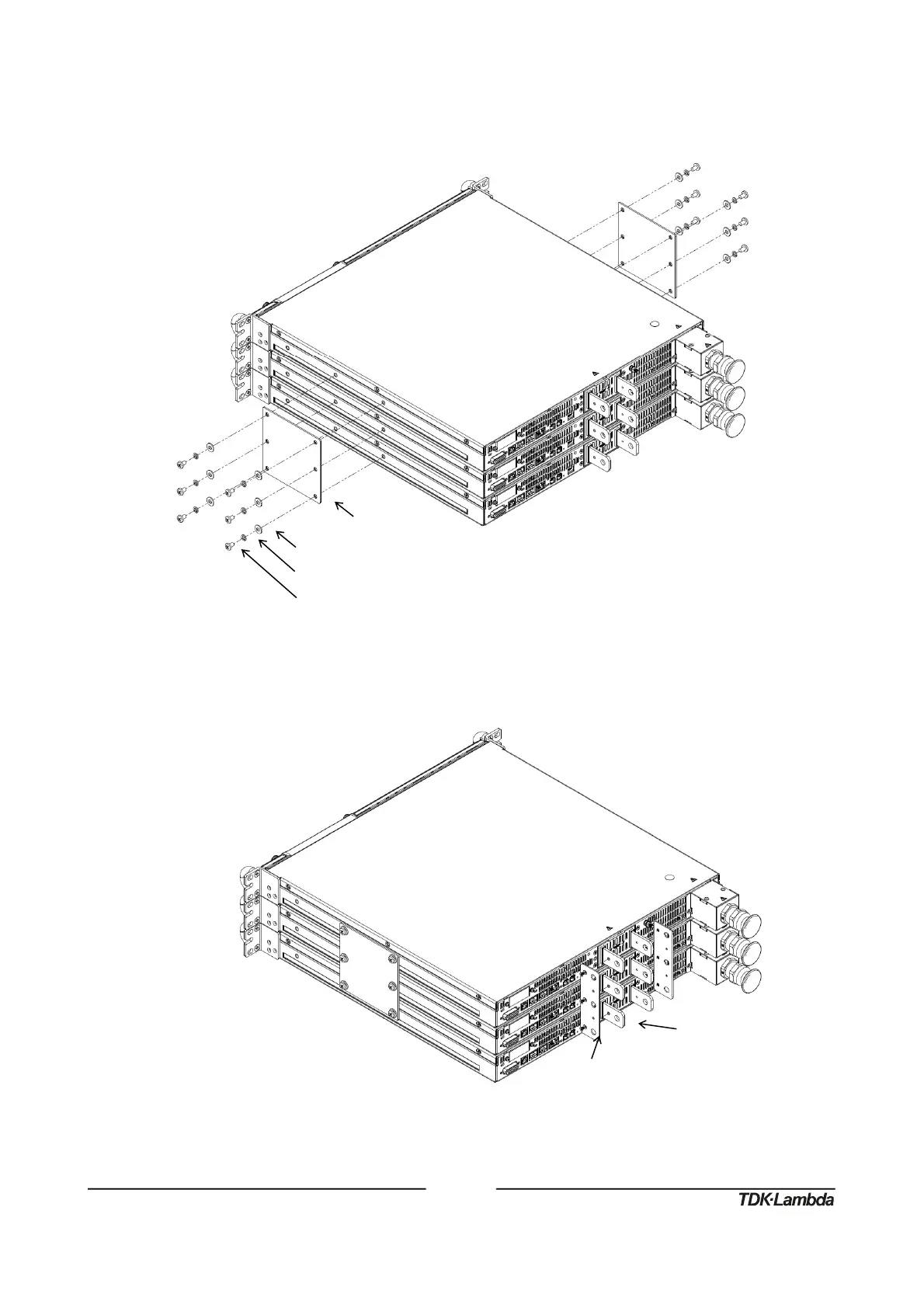
Installation Steps
1. Attach connection plates, one on each side of the power supplies, using 12 pan head screws,
12 helical spring-lock washers and 12 plain washers as illustrated in Figure 16.
Figure16:Three
60V‐100V
UnitsConnectionPlates3UAssembly
2. Attach output short plates, one on each pair of terminals, using six flat head screws as
illustrated in Figure 17.
Figure17:Three
60V‐100V
UnitsOutputShortPlatesAssembly
PlainWasher,No.10,StainlessSteel
HelicalSpring‐LockWasher,No.10,StainlessSteel
10‐32x5/16PanHeadScrew,StainlessSteel
Tighteningtorque:25.4‐31.7Lbf‐inch(2.87‐3.58Nm).
M3x4CFlatHeadScrew,NickelPlated
Tighteningtorque:4.7‐5.7Lbf‐inch(0.53‐0.64Nm)