21
1.4.4.2
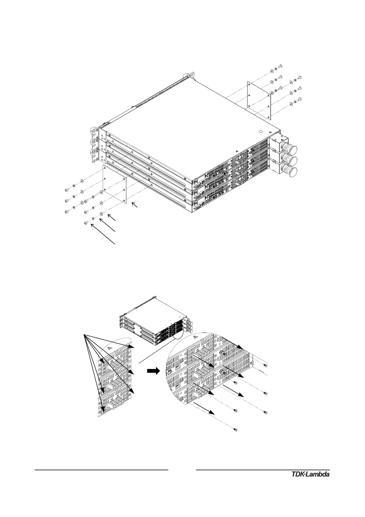
Installation Steps
1. Attach connection plates, one on each side of the power supplies, using 12 pan head screws,
12 helical spring-lock washers and 12 plain washers as illustrated in Figure 23.
Figure23:Three150V‐600VUnitsConnectionPlates2UAssembly
2. Loose and remove six flat head screws from power supply’s back side as illustrated in
Figure 24.
Figure24:Powersupply’sbacksidescrewsremoval
PlainWasher,No.10,StainlessSteel
HelicalSpring‐LockWasher,No.10,StainlessSteel
10‐32x5/16PanHeadScrew,StainlessSteel
Tighteningtorque:25.4‐31.7Lbf‐inch(2.87‐3.58Nm).