114-94438 REV C1
6.2. Assembly configuration cable exit
The inlet can be assembled with different cable exit directions.The required configaration can be
chosen according to customer requirement.
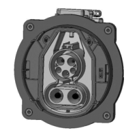
Configurations for cable exit AC 90° sidewards:
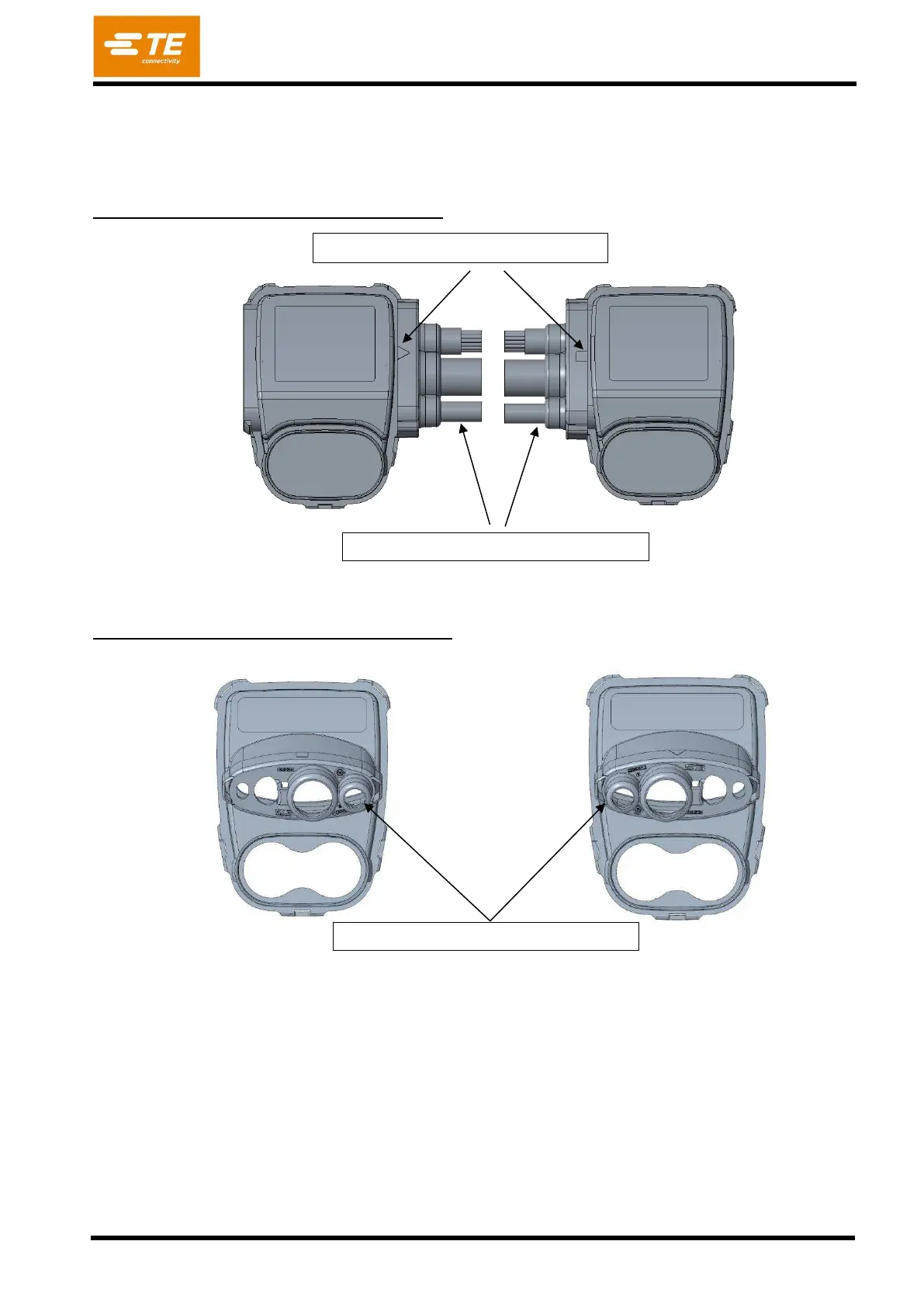
Configurations for cable exit AC 20° downwards:
6.3. Parts to order
See 2.1.a
Attention of symbol triangle and rectangle
PE cable must be always in lower position
PE cable can be chosen left/right