APPENDIX 2 INTERFACE
ENGLISH VERSION
2- 1
APPENDIX 2 INTERFACE
APPENDIX 2 INTERFACE
Interface Cables
To prevent radiation and reception of electrical noise, the interface cables must meet the following
requirements:
Fully shielded and fitted with metal or metallized connector housings.
Keep as short as possible.
Should not be bundled tightly with power cords.
Should not be tied to power line conduits.
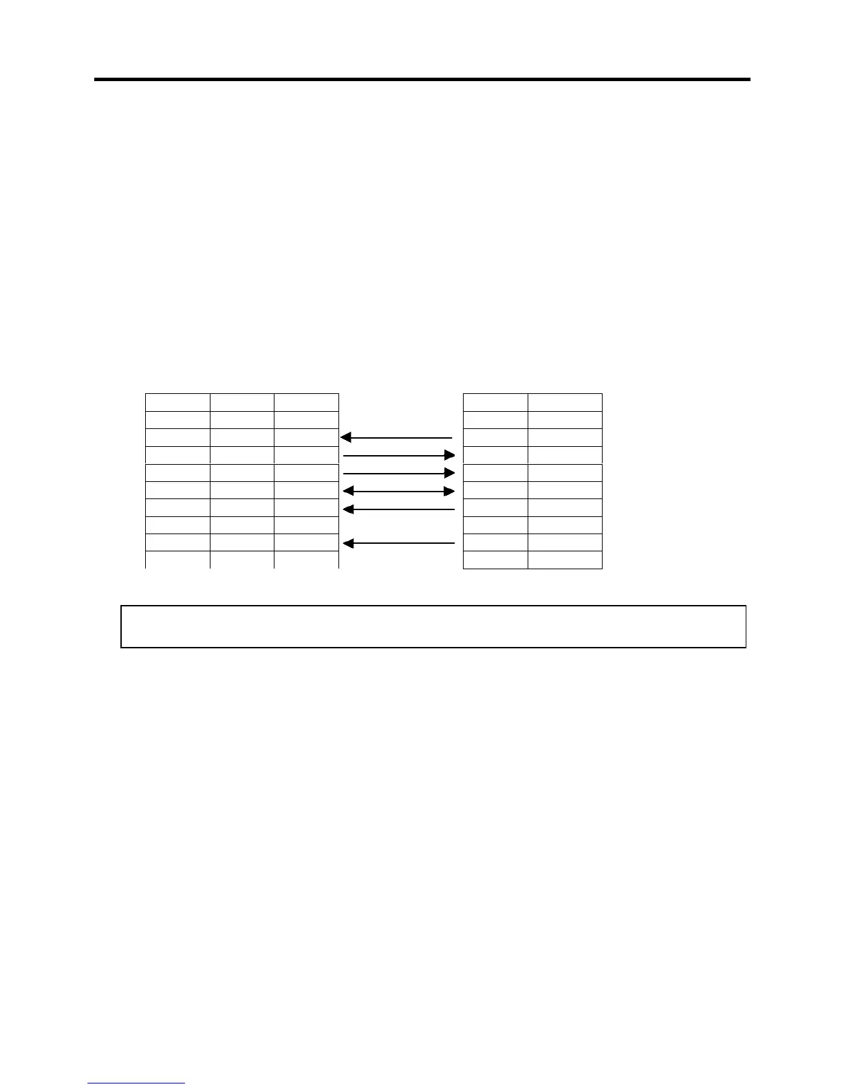
RS-232C Cable description
The serial data cable used to connect the printer to a host computer should be one of the following two
types (9-pin or 25-pin connector):
Connector to the Host Computer
Connector to Printer
NOTE:
Use an RS-232C cable with a connector with inch type securing screws.
Pin No. Function
1 +5V
2 TXD
3 RXD
4 RTS
5 GND
6 CTS
7 RTS
8 CTS
9 +5V
Function 9 pin 25 pin
RXD 2 3
TXD 3 2
DTR 4 20
GND 5 7
DSR 6 6
RTS 7 4
CTS 8 5