Chapter 1 Feature Summary
1.4 Input/Output Ports on the DG-700
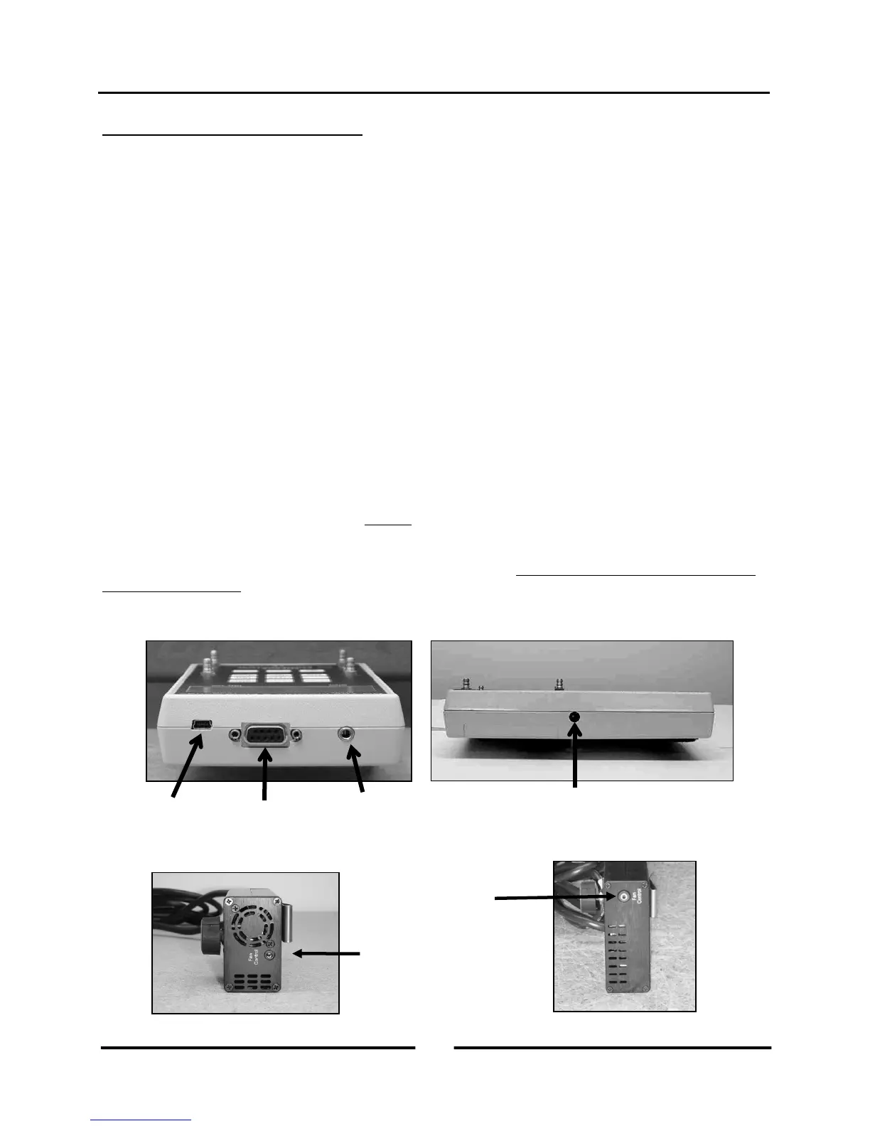
1.4.a USB and Serial Communication Ports:
The DG-700 contains both a USB and a DB-9 serial communication port, either of which can be used to create a 2-
way communication link between the gauge and a computer. This communication link can be used (along with TEC
software) to conduct automated Blower Door tests and to data log both pressure channels.
- Automated Blower Door testing requires the TECTITE, TECTITE Express or TECLOG2 software, a Blower
Door fan speed controller with a communication jack (standard equipment since September 2004), a fan control
cable, and a communication cable (either USB or 9 pin serial) to connect the DG-700 to a user supplied laptop
computer.
- Data logging of pressure measurements requires the TECLOG2 software (available from
www.energyconservatory.com), and a communication cable (either USB or 9 pin serial) to connect the DG-700
to a user supplied laptop computer.
1.4.b Fan Control Output Jack:
The fan control output jack provides a speed control signal which is used to control a Blower Door or Duct Blaster
fan during an automated Blower Door test, or with the Cruise Control feature. A fan control cable is used to connect
the fan control output jack to the communication jack on the side of the fan speed controller.
1.4.c AC Power Input Jack:
The AC power input jack can be used with an optional AC power supply to provide a long term power source for the
gauge (to be used when data logging). The gauge is normally powered by 6 AA batteries located in the rear battery
compartment. When the AC power supply is plugged in, the power supply bypasses the batteries in the battery
compartment. See Chapter 7 for AC power supply specifications. Note: Always turn off the gauge before plugging
in the AC power supply.
Communication
Port
Output Jack
Communication
Port
(Blower Door and
Duct Blaster Speed
Controllers)
4
Operating Instructions
for the DG700