Chapter 4 Pressure/Flow @ 50 and @ 25 Modes
Chapter 4 Pressure/Flow @ 50 and @ 25 Modes
4.1 Mode Summary
(PR/ FL @50)
one-point Blower
Door building
Building pressure in Pascals.
Building leakage at 50 Pascals in units
chosen (CFM@50, m
3
/h@50, l/s@50,
in
2
@50, cm
2
@50).
(PR/ FL @25)
one-point total
leakage duct
Duct system pressure in Pascals.
Total duct leakage at 25 Pa in units
chosen (CFM@25, m
3
/h@25, l/s@25,
in
2
@25, cm
2
@25).
Note: Appendix A contains Quick Guides for using the DG-700 to conduct one-point building and duct system
airtightness tests using the @50 and @25 features.
4.2 Overview of Pressure/Flow @ 50 and @ 25 Modes
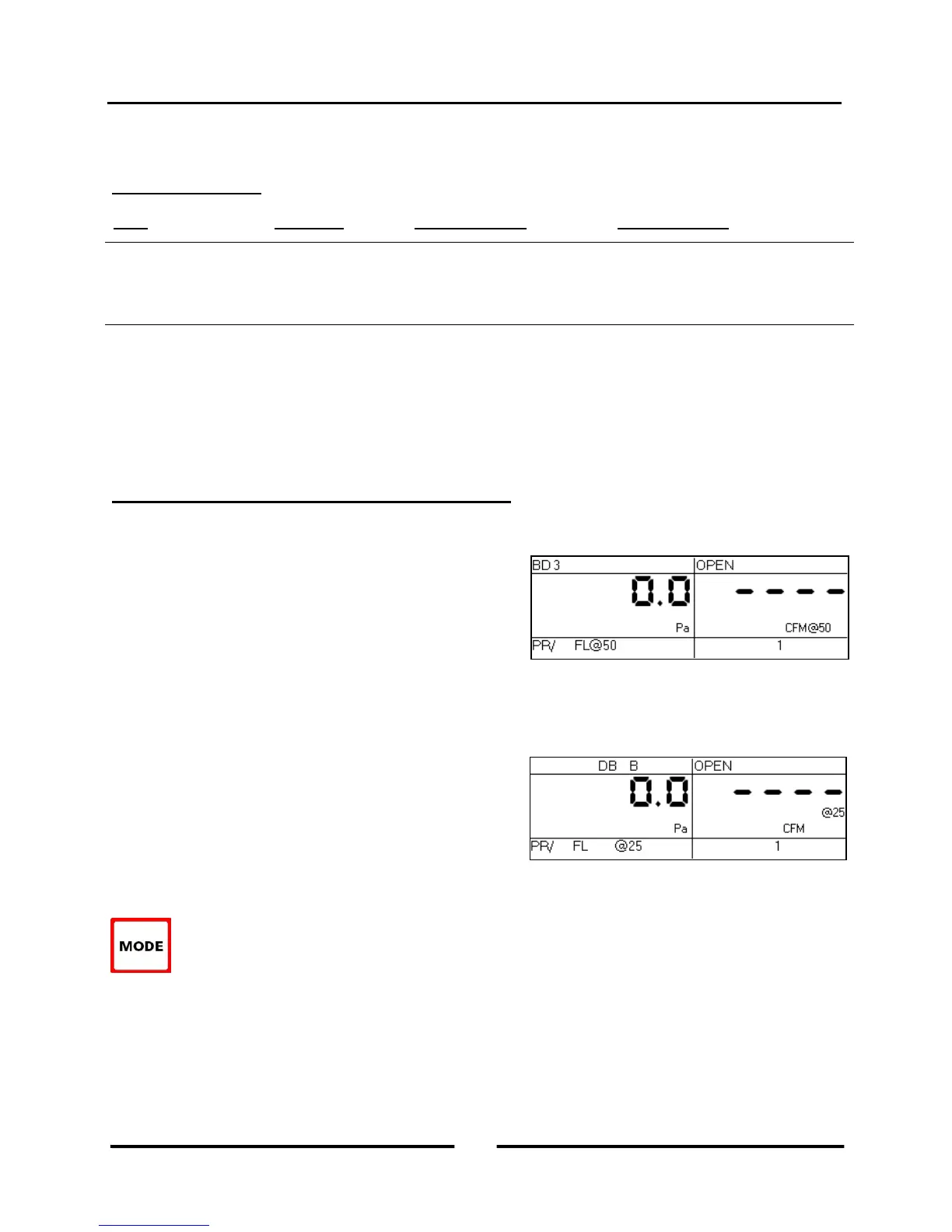
4.2.a Pressure/Flow @ 50 Mode:
The Pressure/Flow @ 50 mode is used to conduct a one-point
Blower Door building airtightness test. In this mode, Channel A
is used to measure building pressure while Channel B is used to
display estimated building leakage at a test pressure of 50
Pascals. The leakage estimate shown on Channel B is
determined by mathematically adjusting the measured air flow
from the selected Blower Door fan using the real-time Channel A building pressure reading and a Can’t Reach
Pressure factor (see Section 4.8 below).
4.2.b Pressure/Flow @ 25 Mode:
The Pressure/Flow @ 25 mode is a specialized mode used for
conducting a one-point total leakage duct airtightness test. In this
mode, Channel A is used to measure duct system pressure while
Channel B is used to display estimated total duct leakage at a
test pressure of 25 Pascals. The leakage estimate shown on
Channel B is determined by mathematically adjusting the
measured air flow from the selected Duct Blaster fan using the real-time Channel A duct system pressure reading
and a Can’t Reach Pressure factor (see Section 4.8 below).
To select the Pressure/Flow @ 50 or @ 25 modes, press the MODE button until the selected operating
mode shown on the gauge display is PR/ FL @50 or PR/ FL @25. When first entering either of these
two modes, the default pressure units on Channel A is Pascals, the default leakage units on Channel B is
CFM @ 50 or 25, and the default time averaging period is 1 second average.
14
Operating Instructions
for the DG700