Chapter 4 Pressure/Flow @ 50 and @ 25 Modes
4.5 Changing the Leakage Units
When in the Pressure/Flow @ 50 or @ 25 operating modes, the DG-700 can display leakage results on
Channel B in units of CFM@, m
3
/hr@, l/s@, in
2
@, and cm
2
@. The default air flow unit is CFM@.
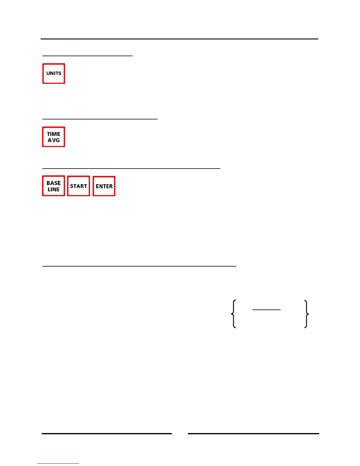
To change the leakage units for Channel B, press the UNITS button. The selected leakage units are
shown on the gauge display directly below the Channel B readings. The pressure unit for Channel A is always
Pascals when in the Pressure/Flow @ 50 or @ 25 modes.
4.6 Changing the Time Averaging Period
To change the selected time averaging period for both Channel A and B, press the TIME AVG button.
The selected time averaging period is shown in the TIME AVG portion of the gauge display. (See
Section 1.5 for an overview of the time averaging periods.)
4.7 Using the Baseline Pressure Feature in Pressure/Flow Mode
The BASELINE feature on Channel A allows the user to measure and record a
baseline pressure reading, and then display the baseline adjusted pressure reading.
This feature is commonly used during both building and duct airtightness test
procedures where the user wishes to display the actual change in building or duct pressure caused by operation of the
Blower Door or duct airtightness testing fan. In order to accurately determine the change in pressure from the test
fan, the user first needs to know the building or duct system pressure (with reference to outside) prior to the test fan
being turned on. This initial baseline pressure reading can be quickly measured and then used to adjust the test
pressure readings to determine the actual change in pressure caused by operation of the Blower Door or duct
airtightness test fan. (See Sections 1.6, 2.5 and 3.7 for a description and examples on how to use the Baseline
feature.)
4.8 Leakage Estimate Calculations Used in the @ 50 and @ 25 Modes
4.8.a @ 50 Mode:
The following equation is used to estimate leakage rates when in the @ 50 mode:
The following equation is used to estimate leakage area when in the @ 50 mode (square inches):
Current Test Pressure (Pa)
(Channel A)
(Channel B)
Door Air Flow Rate
(Channel B)
Rate
(CFM50)
16
Operating Instructions
for the DG700