Appendix A Quick Guides for Using the DG-700 with Energy Conservatory Test Devices
c) Install the assembled metering plate into the filter slot. Be sure the front side of the metering plate is facing into
the air flow (front side has two diamond shaped labels on it). The H-channel gasket should provide a seal around the
metering plate - all of the air flow should pass through the metering plate and not around it. Be sure that the ends of
the flexible tubing connections attached to the plate's pressure sensing grids remain out of the filter slot. Occasionally,
drilling holes into the ductwork may be required as a pathway for the ends of the flexible tubing. The flexible tubing
can be passed through one of the plate's metering holes if this helps in getting the tubing ends outside of the filter
slot.
• Obstructions within 6 inches upstream or 2 inches downstream of the metering plate that are blocking air
flow through any of the metering holes may reduce the accuracy of the device.
• If there is an obstruction and there is a spacer attached to the metering plate, try to install the metering plate
so that the spacer is directly in front of the obstruction (this will minimize the effect of the obstruction on
the flow measurement).
• If the metering plate is installed directly downstream of a 90 degree bend in the duct system, and there is a
spacer attached to the plate, install the metering plate so that the spacer is on the inside corner of the bend
(see diagram to right).
d) Close the filter access opening. Be careful not to pinch off the flexible tubing connections. Temporarily seal
around the filter slot cover with masking tape to prevent air leakage. Note: If you are installing the metering plate at
the filter grille of a single return duct system, simply push the plate into the empty filter rack. Make sure that the front
of the metering plate is facing out (into the air flow). Keep the filter grille door open for the remainder of the test.
3. Connect the Metering Plate to the DG-700.
a) Connect the tubing from the installed metering plate to the DG-700. Connect the Red ("total pressure grid")
tubing connection to the Channel B Input pressure tap. Connect the Green ("static pressure grid") tubing connection
to the Channel B Reference pressure tap. The Channel A Input tap should remain connected to the static pressure
probe.
4. Measure the TrueFlow System Operating Pressure (TFSOP) and Adjusted Total Air Handler Flow.
a) Check and adjust if necessary the selected test Device and Configuration shown in the upper part of the gauge
display to match the metering plate installed in Step 2 above. When using the TrueFlow Metering Plates, the Device
icon should always be set to TF, and the Configuration icon should be set to 14 or 20 depending on which metering
plate is installed. Changes to the selected Device and Configuration are made by pressing the DEVICE and
CONFIG buttons.
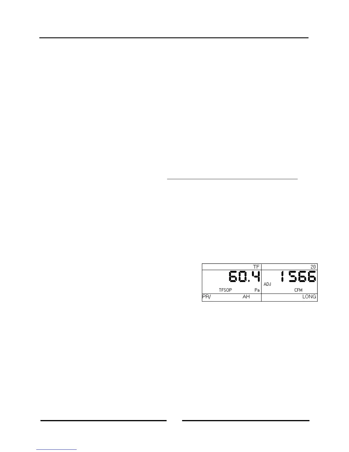
b) Turn the air handler fan back on to the same speed as used in
Step 1 above. Channel A will now display the TFSOP reading
from the static pressure probe, and Channel B will display
adjusted air handler flow. The static pressure probe should be in
exactly the same position as it was in Step 1 above. The air
handler flow rate estimate shown on Channel B is determined by
continuously adjusting the measured air flow from the TrueFlow
Metering Plate using a flow resistance correction factor calculated from the NSOP and TFSOP pressure readings. If
the readings are fluctuating, change the time averaging setting to 5 second, 10 second, or Long-Term average using
the TIME AVG button.
c) Record the adjusted air flow reading from Channel B. In the screen to the right, the adjusted air flow reading is
1,566 CFM. This result is the estimated air flow at the measurement location with the existing filter in place. Turn off
the air handler fan.
Note: When the TrueFlow Air Handler Flow Meter is installed at a remote filter grille, it is possible to make a
correction to the measured flow through the metering plate which increases the accuracy of the flow measurement.
See Appendix C of the TrueFlow manual for more details.
31
Operating Instructions
for the DG700