9
5. Inspect Regulator and hose assembly. Look for any
damage such as abrasions or holes, dirt or debris.
Remove dirt or debris. Replace damaged parts prior
to use.
6. Place the gas cylinder in the space provided in the
base. (See Figure 7.) Remove the protective caps
from Cylinder Valve in grill using the strap provided.
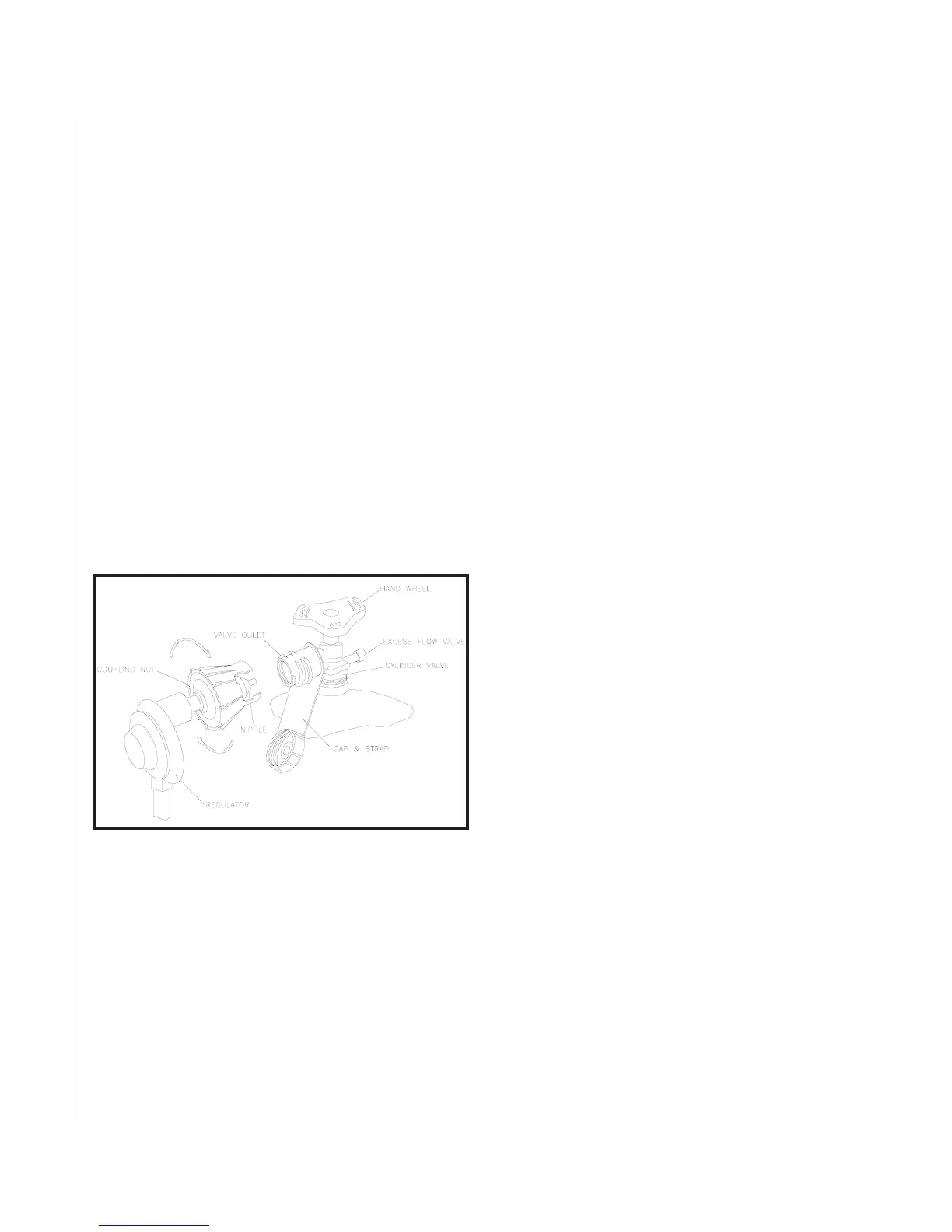
7. With the Regulator in your hand, insert the Nipple
into the Cylinder Valve. (See Figure 8.) Make sure the
Nipple is centered in the Cylinder Valve outlet. Make
sure you do not cross-thread the connection. Tighten
the coupling nut only by hand, do not use tools. As
the connection begins to seal, you will feel a slight
resistance. Turn the coupling nut about one-half to
three quarters of a turn further to complete the
connection. If you cannot complete the final
connection, disconnect the regulator and repeat step
7. If you are still unable to complete the connection,
replace the valve and regulator!
Removing Your LP GAS Cylinder
Procedure:
1. Make sure burner and pilot output knobs are in the
OFF position.
2. Close the Cylinder Valve by turning the Handwheel
clockwise until it stops.
3. Release the latch and remove the cylinder from the grill.
4. Loosen the Coupling Nut by turning it counter-clockwise.
Permanent Installation
CAUTION: GAS PIPING TO YOUR GRILL MUST BE IN
ACCORDANCE WITH LOCAL CODES. IN THE ABSENCE
OF LOCAL CODES, USE THE NATIONAL FUEL GAS
CODE ANSI Z223.1/NFPA 54 (LATEST EDITION) OR
CAN/CGA B-149.1 NATURAL GAS AND PROPANE
INSTALLATION CODE.
CAUTION: THE GAS SUPPLY MUST BE TURNED OFF AT
THE GRILL WHEN THIS APPLIANCE IS NOT IN USE.
When ordered for use with Natural gas, the Patio grill comes
adjusted to operate with Natural gas. Qualified personnel
should install the gas line. A shut-off valve at the grill is
required. This valve must be design-certified by the CSA.
When using the optional Post Base with LP gas, you must use
the regulator and separate hose supplied with the Post Base.
Instructions are provided with the In-ground or Bolt-down
Post Bases. Specifications for gas supply requirements are listed
in Table A.2.
The grill and its individual shut-off valve must be disconnected
from the gas supply piping system during any pressure testing
of that system at test pressures in excess of 1/2 psi (3.5 kPa).
The grill must be isolated from the gas supply piping system by
closing its individual manual shut-off valve during any pressure
testing of the gas supply piping system at test pressures equal to
or less than 1/2 psi (3.5 kPa).
Gas Leak Test
WARNING: DO NOT USE OPEN FLAME TO PERFORM
LEAK TEST!
WARNING: DO NOT ATTEMPT TO USE THE GRILL
WHEN YOU SMELL GAS OR FAIL A GAS LEAK TEST.
Make sure there is no open flame near the grill during the test.
Test for leaks every time the gas connection is disconnected.
Procedure:
1. Turn all controls OFF.
2. Open the Gas Supply Valve slowly. Apply soapy water
solution to all connections including factory connections.
3. Look for bubbles around the connections. If bubbles can
be seen at connections, close the Valve and tighten the
connections where the bubbles were found. If components
are leaking because of damage, replace defective
components. Then, repeat steps 1 and 2 until no leaks are
present. Make sure you do not over-tighten the
connections.
4. Proceed with grill use.
Gas Connection continued
Figure 8. Coupling Assembly