5
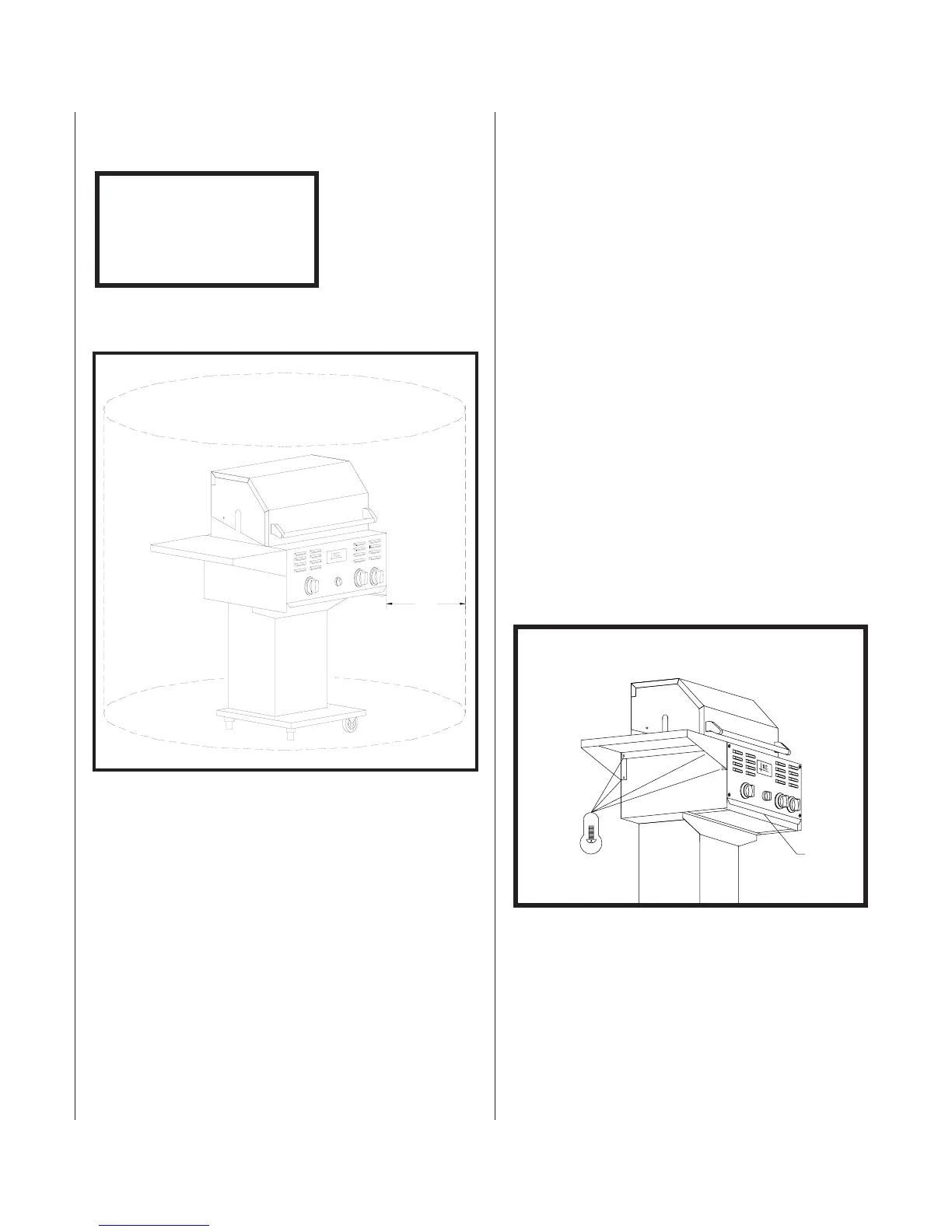
Table A.1 Clearance Specifications
The Post Base is designed to be installed in a bed of
concrete to a depth of 17 1/2”. The height of the grill
cooking surface should be roughly 38 1/2” from the
ground. The gas connection is located on the left side of
the post. The gas connection is 3/8” SAE 45
0
female flare.
WARNING: THIS OUTDOOR COOKING GAS APPLIANCE
SHALL NOT BE USED UNDER OVERHEAD
COMBUSTIBLE CONSTRUCTION.
General Overview
The Patio II™ gas grill is designed for easy assembly.
The Patio II™ grill is available with three base mounting
options. Assembly procedures for each of these options
follow.
Tools Required
■ Phillips screwdriver (#2)
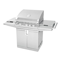
Side Shelf
1. Remove the Side Shelf from shipping box.
2. Remove the upper (2) 1/4 - 20 x 5/8 long Phillips-
head bolts from the grill housing.
3. Loosen the lower (2) Phillips-head bolts in the grill
housing. Do not remove the lower bolts.
4. Mount the Side Shelf onto the lower bolts loosened
in step 3 above.
5. Insert (2) Phillips-head bolts into the upper holes.
6. Tighten all (4) bolts securely.
Figure 2. Side Shelf (new style)
COMBUSTIBLE
CONSTRUCTION
Sides 12”
Back 12”
Installation
continued Assembly
DRIP TRAY
1/4-20 PHILLIPS
BOLT (TYP. 4
PLACES)
Figure 1. Clearance Specifications
12”