12
Revised 08/04
-- Z21.58b/CGA1.6b-2002
Pilot Flame Adjustment
The pilot flame length is preset at the factory, but can be
adjusted. The flame length should be approximately one
inch from the hood covering the pilot burner. Make sure
the burner is not in operation and that all other gas
valves are OFF prior to adjusting the pilot. This
procedure should not be performed while the grill is hot.
Use a small
1
/
8
” flat-blade screwdriver and the following
procedure to make pilot adjustments.
Procedure:
1. Ignite the pilot following Steps 1 through 4 of the
Burner Ignition Procedure.
2. Remove the Pilot Output Knob from the valve stem.
3. Insert a
1
/
8
” flat blade screwdriver into the valve
stem.
4. While visually observing the pilot flame, rotate the
pilot adjustment screw counter-clockwise to increase
the flame length or clockwise to decrease the flame
length. The flame should be approximately one-inch
long. (See Figure 13.)
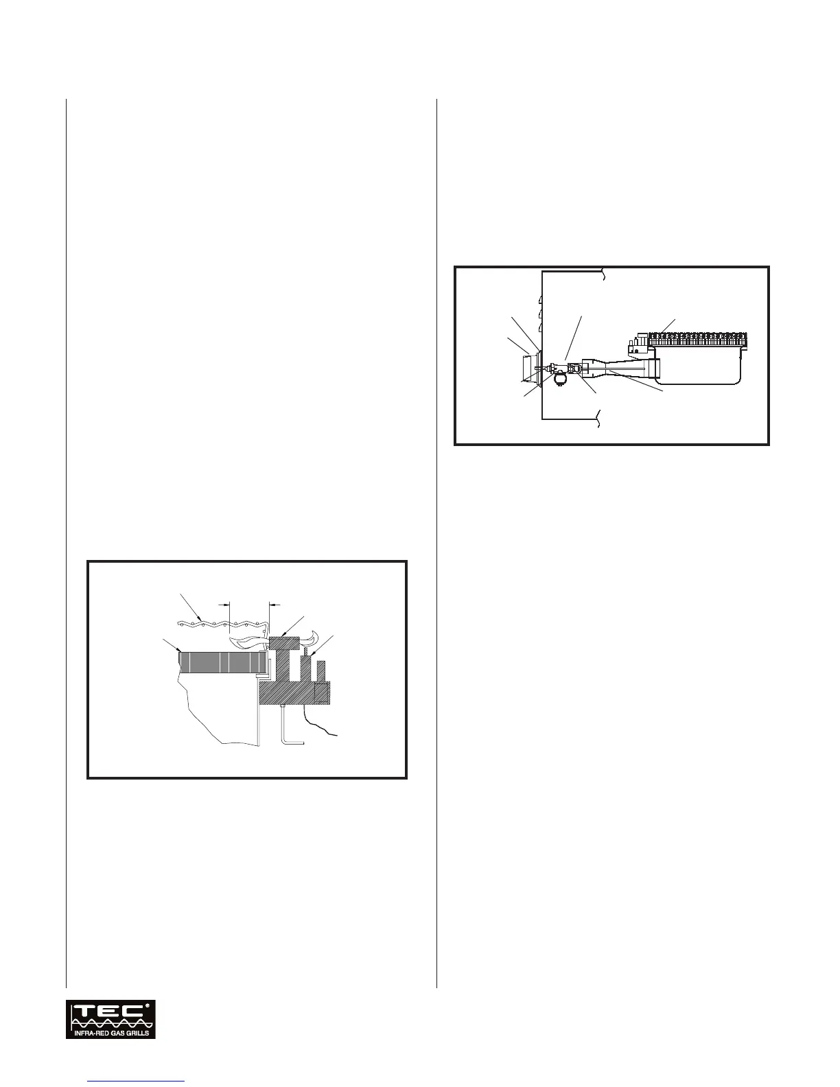
Burner Flame
The burner flame should be approximately 1/2” tall
when the burner is in operation (See Figure 13a).
WARNING: EACH GAS ORIFICE MUST BE PROPERLY
LOCATED ON THE ORIFICE BRACKET, ATTACHED TO
THE VENTURI ON THE BURNER ASSEMBLY. AN
IMPROPERLY LOCATED ORIFICE CAN LEAD TO BODILY
INJURY AND PROPERTY DAMAGE. THE PROPER
LOCATION IS SHOWN IN FIGURE 13A.
Hazardous Locations
and Conditions
■ When cooking, keep your grill at least one foot from
combustible surfaces (wood wall or wooden fence,
etc.) and from under combustible material (i.e.
wood, canvas, plastic, etc.).
■ Do not block the flow of combustion and ventilation air.
■ Only use your grill outside in a well-ventilated area. Do
not cook in a building, garage, or other enclosed area.
■ Keep flammable substances away from the grill,
including spare gas cylinders, aerosols and aerosol
containers, gasoline and similar liquids, paper and
paper products, containers of grease, paint, etc.
■ Never leave your grill unattended while it is on.
■ Never use water to control a flare-up.
■ Do not wear flammable and/or loose clothing, such
as neckties, scarves, etc., while using the grill.
Operation
continued
Figure 13a. Burner Flame and Orifice Location
1/2” Approx. Flame Length
Orifice Jam Nut
Venturi
Orifice
Bezel
Control Knob
Gas Valve
Gas Manifold
Figure 13. Pilot Light Adjustment