22
nd
October 2004 SC2000 Manual – 177/52301 Rev G Page 45
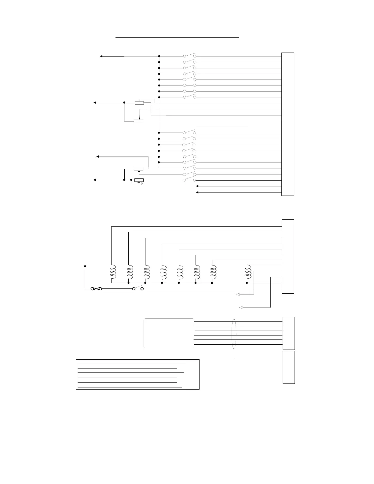
Fig. 1 - Control Wiring Diagram
1
2
3
4
5
6
7
8
9
10
11
12
13
14
15
16
17
18
19
20
21
22
23
24
Connector A
1
2
3
4
5
6
7
8
9
10
11
12
Connector B
To Main
Fuse
Keyswitch
LINE
FORWARD
REVERSE
REGEN
BYPASS (T)
F/WEAK.
P/STEER
PMP BYP
(Contactor suppression
fitted internally)
10A Fuse
(DM RIGHT FWD)
(DM RIGHT REV)
(DM LEFT FWD)
(DM LEFT REV)
Reverse Sw
FS1 Sw
Seat Sw
Handbrake Sw
Speed Cutback 1 Sw
Speed Cutback 2 Sw (DM outer sw)
Pump inhibit i/p
Forward Sw
Pump Sw 3
Pump Sw 4
Pump Sw 5
Pump Sw 6 (Inch Fwd/DM inner L)
Pump Sw 2
Pump Sw 7 (Inch Rev/DM inner R)
Power steer trigger input
Speed sensor input
Analogue 2 input
Analogue2
(wired as 3 wire system)
Analogue 1 input
Analogue 2 supply
Analogue 1 supply
Analogue1
(wired as 3 wire system)
To B-ve for Active low or
Keysw for Active high
B-ve
B-ve
Analogue3
(wired as 2 wire system)
Keysw
Analogue4
(e.g Hall effect unit)
(wired as voltage source)
(deriving own +ve supply)
Analogue 4 supply
B-ve
Nominal +12V o/p
To regen contactor wiper
-- Reserved Clean BDI i/p --
1
2
3
4
5
6
Connector C
CALIBRATOR
or DISPLAY
Cable supplied
with Calibrator/
Display
1
2
3
4
5
6
Connector D
FLD. WK.
Analogue 4 input
on all units except SC24xx
Analogue 3 input
/(DM
BAL cont)
Unit Analogue1 Analogue2 Analogue3 Analogue4
SC22XX Traction Footbrake Economy Not Used
SC23XX Not Used Not Used Not Used Pump
SC24XX Traction Steer Pot Footbrake Pump
SC25XX Traction Steer Pot Footbrake Economy
SC22XX Traction Footbrake Economy Pump