22
nd
October 2004 SC2000 Manual – 177/52301 Rev G Page 31
10.3 GENERAL OPERATION
10.3.1 Operating Frequency
The drive frequency of both the Traction and Pump power frames is 15.67Khz, for silent
operation. For Traction plug and regen-braking the frequency is also 15.67Khz and silent.
10.3.2 Temperature Monitoring
If the temperature of either power frame exceeds 75
o
C its maximum available current will be
reduced. Note, however, that if the set current limit is less than the maximum available
current limit actual cutback will occur at progressively higher temperatures than 75oC. The
thermal cutback ensures that the maximum heatsink temperature is limited to 95
o
C (See
Graph 1). When actual cutback occurs the diagnostic LED will flash 8 times. Inspection of the
calibrator fault messages will indicate which unit is in thermal cutback.
10.3.3 Safe Operating Area (SOA)
The controller’s current may be limited at high and/or low duty cycles depending on its current
and voltage specification. This is to reduce the thermal stress on the power components in
order to increase long term reliability. See Graph 2.
The “Safe Operating Area” is a characteristic of the MOSFETs and Freewheel Diodes which
make up the powerframe. The MOSFET SOA restricts current at high duty cycles on all
configurations, and the Diode SOA tends to restrict the current at lower duty cycles on lower
voltage applications.
For most applications SOA will have little or no effect on the operation of the controller. It’s
effect is more significant in protecting the controller against adverse loads such as damaged
motors and static test rigs.
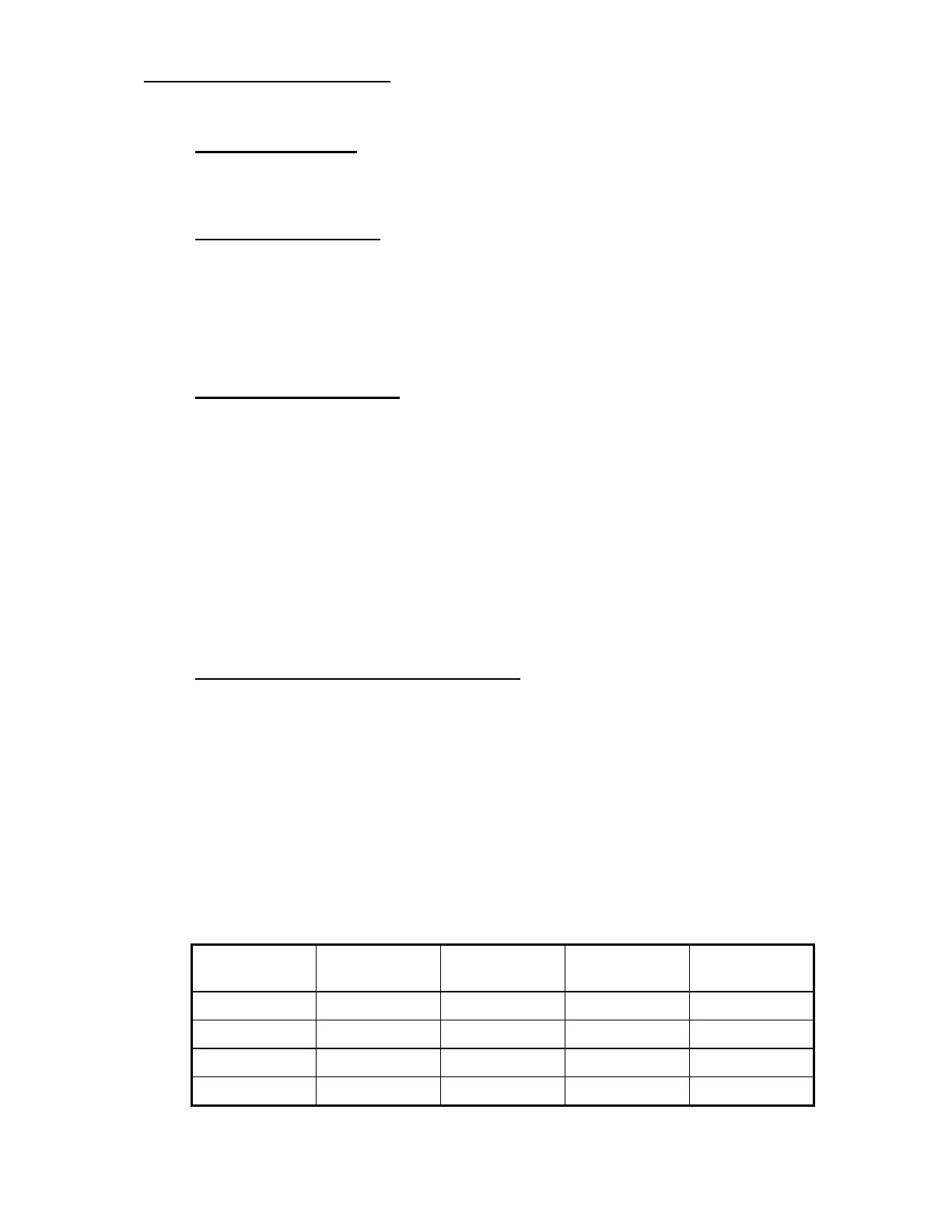
10.3.4 Under-voltage and over-voltage protection
In order to prevent a sudden loss in power, the controller will begin to linearly ramp down the
current limit, once the average battery voltage falls below a pre-set under-voltage start level.
The current will be ramped down to 0 and a 7 flash fault indicated if the averaged battery
voltage falls below the under-voltage cut-out level.
To protect the controller from over-voltage caused by prolonged regen braking the regen
current is cutback linearly from 100% when the average battery voltage reaches the over-
voltage start level, to the minimum braking level at the over-voltage cut-out level.
If the battery voltage exceeds the over-voltage cutout level, all pulsing is stopped and a 7-
flash fault is indicated. This protects against incorrect battery connection.
Nominal
Battery Voltage
Under-voltage
Cutout
Under-Voltage
Start
Over-voltage
Start
Over-voltage
Cutout
24 V 14.5 V 18.0 V 40.0 V 45.0 V
48 V 14.5 V 18.0 V 65.0 V 70.0 V
80 V 43.0 V 60.0 V 95.0 V 100.0 V
96 V 43.0 V 60.0 V 120.0 V 125.0 V