RST10
Ref.
No.
4
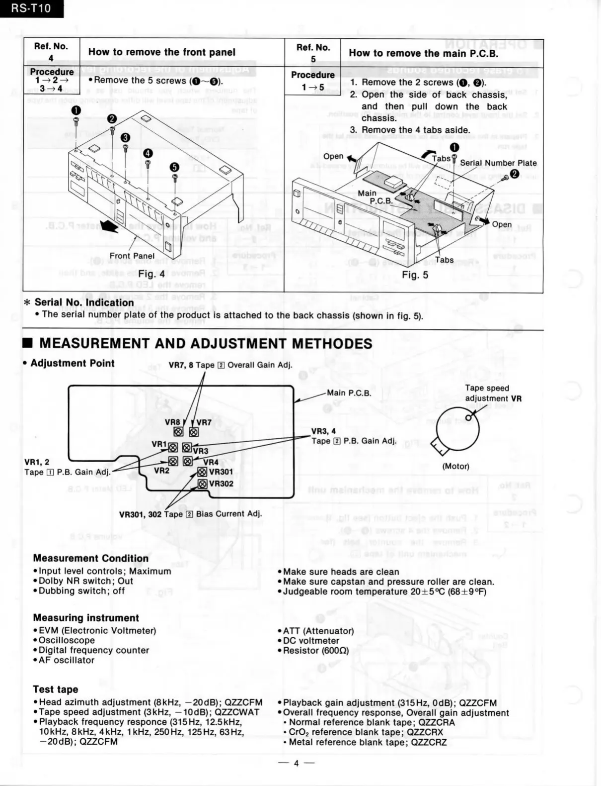
How
to
remove
the
front panel
Ref.
No.
5
How
to
remove
the
main P.C.B.
Procedure
3^4
•Remove
the 5
screws
(O—©).
Front Panel
rierij
bn Fig. 4
vuiüsH
.i,
Procedure
1^5
1.
Remove
the 2
screws
(O, ©)•
2.
Open
the
side
of
bacl< chassis,
and then pull down
the
back
chassis.
3. Remove
the 4
tabs aside.
Serial Number Plate
Fig.
5
* Serial
No.
Indication
•
The
serial number plate
of the
product
is
attached
to the
back chassis (shown
in fig. 5).
I MEASUREM ENT
AND
ADJUSTM ENT METHODES
Adjustment Point
VR7,
8
Tape
m
Overall Galn
Adj.
VR1,
2
Tape
H P.B.
Gain
Adj.-
^
VR301,
302 tape
H]
Bias Current
Adj.
.a,0,«i amufoV-
Measurement Condltion
• Input level controls; Maximum
•Dolby
NR
switch;
Out
• Dubbing switch;
off
Main P.C.B.
VR3,
4
Tape
[H P.B.
Gain
Adj.
• K ï t )
Tape speed
adjustment
VR
(Motor)
.oM.iafi
•R
e;
:-iTl
• Make sure heads
are
clean
• Make sure capstan
and
pressure roller
are
clean.
•Judgeable room temperature 20±5°C (68+9°F)
O'
Measuring instrument
• EVM (Electronic Voltmeter)
• Oscilloscope
•Digital frequency counter
• AF oscillator
Test tape
• Head azimuth adjustment (8kHz, -20dB); QZZCFM
•Tape speed adjustment (3kHz, -10dB); QZZCWAT
• Playback frequency responce (315 Hz, 12.5kHz,
10kHz, 8kHz, 4kHz, 1 kHz, 250Hz, 125Hz, 63Hz,
-20dB);
QZZCFM
• ATT (Attenuator)
• DG voltmeter
• Resistor (600Q)
% 0
•Playback gain adjustment (315Hz, OdB); QZZCFM
• Overall frequency response. Overall gain adjustment
• Normal reference blank tape; QZZCRA
_
•
CrOs reference blank tape; QZZCRX
• Metal reference blank tape; QZZCRZ
—
4 —