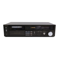
RS-X933
@
CONTENTS
*Location
of
Controls...........
Hot
to
Connection
...............
¢
Disassembly
Instructions
¢Information
on
Power
Supply
Jig
...........:::secseeees
9
Measurement
and
Adjustment
Methodes.....
10~12
¢Terminal
Function
of
IC’s
¢
Printed
Circuit
Boards.................0
Schematic
Diagram............ccccccccesesssesesseeeees
li
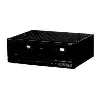
LOCATION
OF
CONTROLS
1
2) [3
[1]
Power
on/off
switch
(POWER)
sat
ceaLacascecconsceecssaces
ssssseeeeees
(E,
E5,
GC,
GN)
areas.
Power
on/stanby
(!)
switch
(POWER)
dunce
cacessadsdesassneuenieesdcndadcecucteaveaapavavesaceaaue
(EG)
area.
Deck
on/off
switch
(DECK)................
(EB)
area.
[2]
Timer
switch
({)
TIMER)
This
switch
can
be
used
to
automatically
begin
a
tape
recor-
ding
or
tape
playback
at
a
certain
time,
selected
by
an
op-
tional
timer.
[3]Reverse-mode
selector
(REVERSE
MODE)
This
selector
can
be
used
for
selection
of
the
reverse
mode
(for
either
playback
or
recording).
[4]
Tape
counter
(DECK
A
COUNTER)
Indicates
the
amount
of
tape
movement.
[5]
Tape
counter
reset
button
(RESET)
This
button
can
be
used
to
reset
the
tape
counter
indication
to
“O00”.
Page
¢
Terminal
Guide
of
IC’s,
Transistors
and
Diodes..............cccccscsssssseseees
25
©
Block
Diagram.
...........ccccssscsessssesseseeessenssesensaees
26,
27
Wiring
Connection
Diagram
..............cccccsssssseeeee
28
Resistors
&
Capacitors.............cccsessseserenreees
29~32
Replacement
Parts
List
(Electrical
Parts).....
33~35
Mechanical
Parts
Location
(DECK
A).............
36,
37
e
Replacement
Parts
List
(Mechanical
Parts)
..............ccccsscessssssersees
Mechanical
Parts
Location
(DECK
B)
is
Cabinet
Parts
Location.
............:.ccseccsessseenseees
[6]Input
level
meter
(PEAK
LEVEL)
During
tape
playback,
this
meter
indicates
the
level
of
the
recorded
sound
source.
During
recording,
it
indicates
the
level
to
which
the
record-
ing-level
control
has
been
adjusted.
Dolby
noise-reduction
buttons/indicators
(DOLBY
NR)
These
buttons
can
be
used
to
reduce
the
hiss
noise
that
is
characteristic
of
tape.
This
unit
is
provided
with
both
the
B-type
and
C-type
noise-reduction
systems.
Edit-recording
tape-speed
buttons/
indicators
(EDIT
SPEED)
These
buttons
can
be
used
to
select
the
recording
speed
when
a
tape-to-tape
recording
is
made.
[9]Synchro-start
button
(SYNCHRO
START)
This
button
can
be
used
to
start
a
tape-to-tape
recording,
simultaneously
starting
tape
deck
B
(the
playback
deck)
and
tape
deck
A
(the
recording
deck).
[10]
Recording-level
control
(REC
LEVEL)
This
control
can
be
used
to
regulate
the
recording
level
of
tape
deck
A.