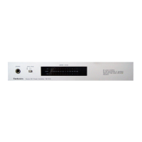
SE-CH610
m@
Contents
Page
Page
BIOL
eS
RCD
aN
tei
sscetscsectet
lca
pa
asada
ing
te
cee
Gree
ee
naan,
2
Power
Source
ON/OFF:
of
THIS:
Witt
dccveisisaei
ccd
verntwi
No
acetad
tucerevsecseaten
14
PLOLO
GU
ON
CICUILEY
sei
eccesaaesaurensaased
eaurctnoaete
Rasnaauenememaled
etlnadsaleass
2
SCNEMAUGC
DIAQla
i
ct
snncnucicdrneVaniondin
pied
ueda
seine.
Lie
PCC
SS
SO
CS
ais
ee
ah
pak
cite
laes
Sera
he
Meee
US
nh
oie
baie
ate
at
2
Printed
Circull
Board
Dia
Grainy
acnvcsciasacucssinccesruatgedtncniclectivien
16~18
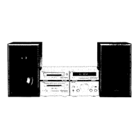
Stacking
the
COMPONEMNES
........cccccsccseeecssssssessesssccsssecsevcescenseveucevseeesers
3
WICKING;
CONNECHON:
DIAGraM
-iecnciorcet
alee
tena
oek,
Dada
aed
aivzele
19
GONMES
CHONG
iste
acti
Sestocvap
ceutontrssancawersy
Docbvinauistnrtendeietacdemedeare
ene
3~7
FUNGCHOR
OIG:
TOMninals
iscsi
ncienlcentc
hatin
echestiada
sates
19
OGALOMOl
GOMUOlS
seicces
ccs
ieeetag
waa
ty
cateostenteconeaiudtticis
dares
unease
pees
oucat
7
BOCK
DIA
QIAN
isc,
veers
ancetsadasand
aly
vodcia
pe
aevaeed
eee
baad
aes
ieaaled
cacao
ole
20
Operation
Check
and
REPIACEMENE
Pans:
LISS
sscosnsactimelsecaudieecstemchecscwiatvomiontaseees
21~24
Main
Component
Replacement
Procedures
wo...
ceees
8~10
Cabinet
Parts
LOCanOn
vis
icidevasnans
viciaxerrvatas
asaorentatacdiu
naman
29
PACKAGING
axe
vi
reteg
hs
toe
in
Gieacsar
es
wens
SA
aya
tina
ees)
Wei
G
eigen
26,
27
@
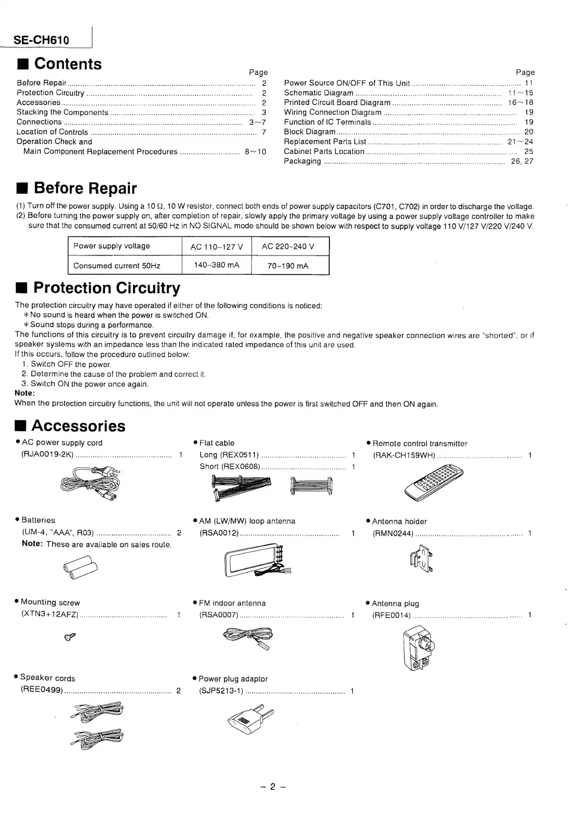
Before
Repair
(1)
Turn
off
the
power
supply.
Using
a
10
2,
10
W
resistor,
connect
both
ends
of
power
supply
capacitors
(C701,
C702)
in
order
to
discharge
the
voltage.
(2)
Before
turning
the
power
supply
on,
after
completion
of
repair,
slowly
apply
the
primary
voltage
by
using
a
power
supply
voltage
controller
to
make
sure
that
the
consumed
current
at
50/60
Hz
in
NO
SIGNAL
mode
should
be
shown
below
with
respect
to
supply
voltage
110
V/127
V/220 V/240
V.
AC
220~240
V
70~190
mA
Power
supply
voltage
AC
110~127
V
140~380
mA
Consumed
current
50Hz
@
Protection
Circuitry
The
protection
circuitry
may
have
operated
if
either
of
the
following
conditions
is
noticed:
*
No
sound
is
heard
when
the
power
is
switched
ON.
*
Sound
stops
during
a
performance.
The
functions
of
this
circuitry
is
to
prevent
circuitry
damage
if,
for
example,
the
positive
and
negative
speaker
connection
wires
are
“shorted”,
or
if
speaker
systems
with
an
impedance
less
than
the
indicated
rated
impedance
of
this
unit
are
used.
If
this
occurs,
follow
the
procedure
outlined
below:
1.
Switch
OFF
the
power.
2.
Determine
the
cause
of
the
problem
and
correct
it.
3.
Switch
ON
the
power
once
again.
Note:
When
the
protection
circuitry
functions,
the
unit
will
not
operate
unless
the
power
is
first
switched
OFF
and
then
ON
again.
M@
Accessories
®
AC
power
supply
cord
®
Flat
cable
®
Remote
control
transmitter
(ASAD
VOR 2K)
icnaciteahined
adcctanenenwtienes
1
EGNG
(AE
AOS
issescsichvis
on
sees
sncaaeraneieuian
j
(RAK-CHTSSWE)
sce
sida
sucudeiivunitscxnet
outa:
1
SHON
(AE
AOS
OE)
sc
iitncotiensnmamatuhadiacan
1
®
Batteries
@
AM
(LW/MW)
loop
antenna
@
Antenna
holder
(UM
4).
“AAA®
ROS)
iii
dtestciscctiruttetvaaaes
2
(RSA0012)
tesa
tececer
eee
eaters
ee
fess
1
(RIMINO
244
hoo
cat
ercissccotiasiascnaeceouk
nies
1
Note:
These
are
available
on
sales
route.
=
SS
®
Mounting
screw
@
FM
indoor
antenna
®@
Antenna
plug
(XTNS+12AFZ)
ooo.
ccccccecccccecseessserseseeees
1
(RSAQO0T)
kaseaieces
Pusat
concasediceattaates
1
CA
EO
Ween
carte
steicytnaaeenateatietinennnaeae
1
tad
@
Speaker
cords
®
Power
plug
adaptor
(REE0499)
2
(SUP
52134)
serine
etre
eiandets
1