FRONT PANEL CONTROLS AND THEIR FUNCTIONS
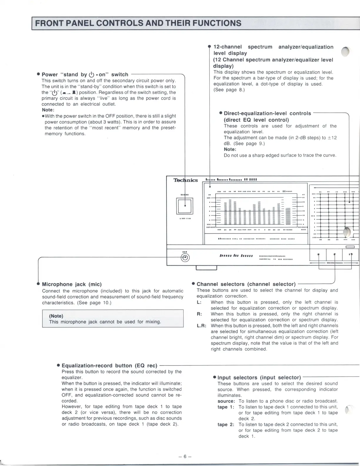
• Power "stand
by
C)
•
on"
switch
---------....
This switch turns on and off the secondary circuit power only.
The unit is in the
"stand-by"
condition when this switch is set to
the
"C)"
(•~
I)
position. Regardless of the switch setting, the
primary circuit is
always
"live"
as long as the power cord is
connected to an
electrical outlet.
Note:
•With
the power switch in the OFF position, there is still a slight
power consumption (about 3 watts). This is in order to assure
the retention of the
"most
recent" memory and the preset-
memory functions.
12-channel spectrum analyzer/equalization
level display
(12 Channel spectrum analyzer/equalizer level
display)
This display shows the spectrum
or
equalization level.
For the spectrum a bar-type
of
display is used; for the
equalization level, a dot-type of display is used.
(See page 8.)
• Direct-equalization-level controls
--
---
-...
(direct EQ level control)
These controls are used for adjustment of the
equalization level.
The adjustment can be made (in 2-dB steps) to ± 12
dB.
(See page 9.)
Note:
Do not use a sharp edged surface to trace the curve.
~mics
•·
..................
••••••
Microphone jack (mic)
Connect the microphone (included) to this jack for automatic
sound-field correction and measurement of sound-field frequency
characteristics.
(See page 1 0.)
(Note)
This microphone
jack
cannot be used for mixing.
Ill
U U
II
ltiiiiiiiiU
If
II II
U
II
lltUit
"
"
"
...
...
.
...
"
...
j~
"
:
!
~
...
" " "
...
1 =
-
-~
::
.~
~~=
=~
=
=
=
.
: - =
:::
= : =
~
~ ~
~ ~
~
~
= =
::
..
:--=-
~
~
~
~
~
~
~
~
~
~
~
~=
~-
:
.......
Ul
II
II
llllltiiUI
II
I
II
U
II
1111111
IIU
lltUII
II
lllo
II
tttnttl
111111
1
11111111111
IIIII
=
,,,,,, ,,, ,,,,,,
..................
.
i I I
·r
---+-
······
······--+--
I
• Channel selectors (channel selector) -
----"'
These buttons are used to select the channel for display and
equalization correction.
L:
When this button is pressed, only th e left channel is
selected for equalization correction or spectrum display.
R. When
th1s
button
1s
pressed, only the right channel
is
selected for equalization correction or spectrum display.
L.R:
When this button is pressed, both the left and right channels
are selected for simultaneous equalization correction (left
channel
bright, right channel dim)
or
spectrum display. For
spectrum
display, note that the value
is
that of the left and
right
channels combined.
• Equalization-record button (EQ rec)
--------------
--
-----
-----
----
-
Press this button to record the sound corrected by the
equalizer.
When the button is pressed, the indicator will illuminate;
when it is pressed once again, the function is switched
OFF, and equalization-corrected sound cannot be re-
corded.
However, for tape editing from tape deck 1 to tape
deck 2 (or vice versa), there
will be no correction
adjustment for previous recordings, such as disc sounds
or radio broadcasts, on tape deck 1 (tape deck 2).
-6-
• Input selectors (input selector)
------
--
-
These buttons are used to select the desired sound
source. When pressed, the corresponding indicator
illuminates.
source: To listen to a phone disc
or
radio broadcast.
tape 1: To
listen to tape deck 1 connected to this unit,
or
for tape editing from tape deck 1 to tape
deck
2.
tape 2: To listen to tape deck 2 connected to this unit,
or
for tape editing from tape deck 2 to tape
deck
1.
 Loading...