• Others
ENCA/B: Sensor encoder input
LINKSD/LINKSK: For control terminals
TTPWM: Turntable clock
SC microcomputer
• Audio output
DSP.DATA/BCK/LRCK/SCK: Audio data, digital output data
• LCD controls
CRDT0 to 7, others
• CD shutter controls
CDOPN/CLS, CDSMO/C: CD shutter detection and motor control
• JTAG.xx: For bug check
• DSP.DTx, GIOx: For MD microcomputer communication
MD microcom
uter
• SRDT0 to 15, Others: For communication with the CD unit and for communication with SDI/F
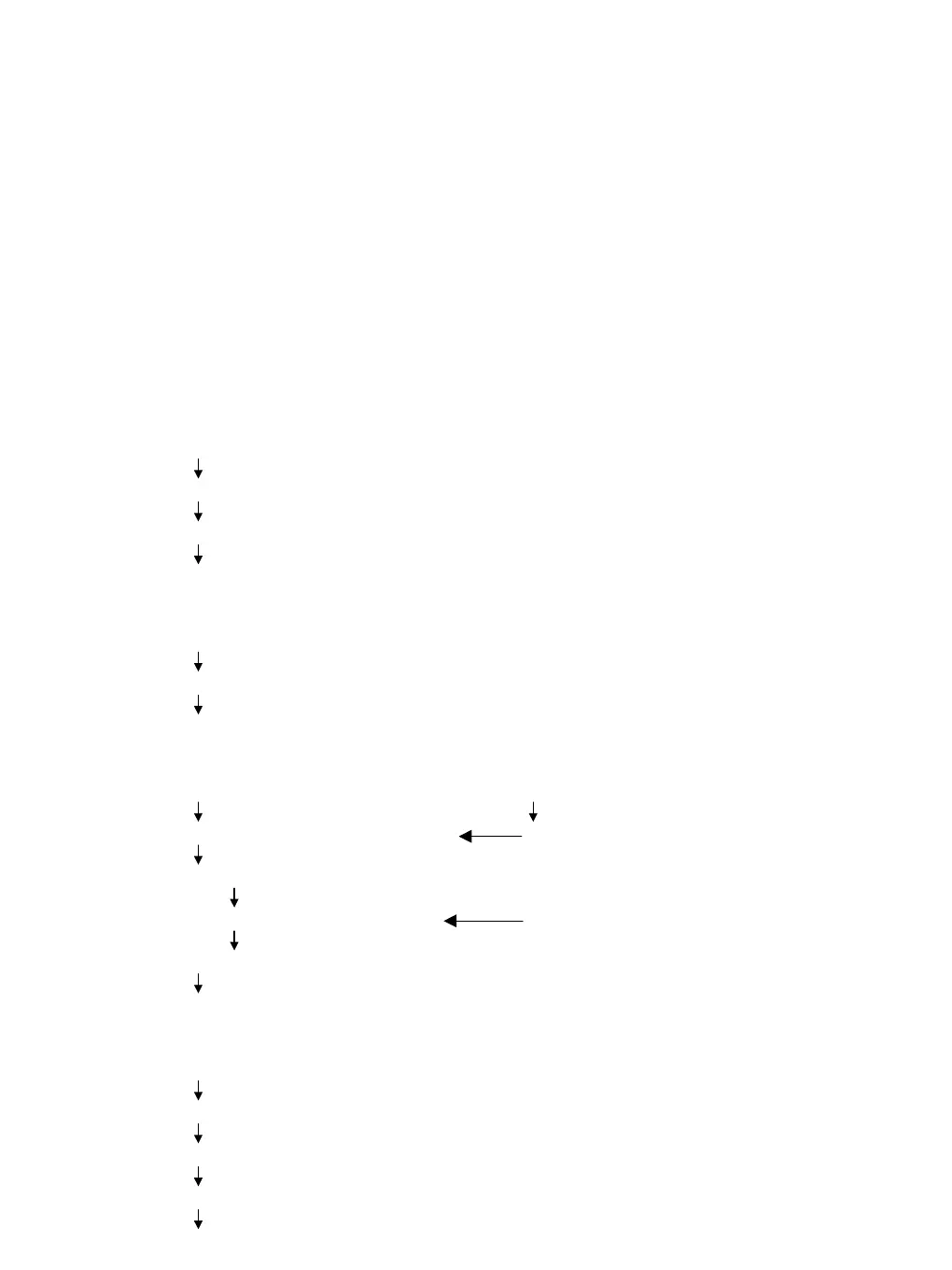
Signal flow:
1. Panel (refer to the block diagram, Fig. 2)
Input signals from CP1, CP2, CP3, CP5, PCON
Input to the A/D input port of the UI microcomputer
LED output and execution of communication with SC
LCD display, audio output, turntable rotation, etc.
2. LED (refer to the block diagram, Fig. 3)
Port output from the UI microcomputer (from data of the above switches etc.)
Data output to CP1, CP3, CP5, STROBE, etc.
Address serial data are concerted to the matrix and LEDs are lit.
3. Audio flow for CD, SD (refer to the block diagram, Fig. 4/5)
CD unit SD slot
MD microcomputer <--> SDRAM SD I/F
Data storage
SC microcomputer <-- UI microcomputer <-- Slip sensor
Audio processing <--> SDRAM Sensor, tempo, REV, FREE
DAC/DIT
Audio output
4. Turntable (turntable mode) (refer to the block diagram, Fig. 6)
Switch input
UI microcomputer
<-- Clock, reverse, start/stop, free-wheel
Motor control IC
Driver IC
Motor <-- Turntable rotation