.--
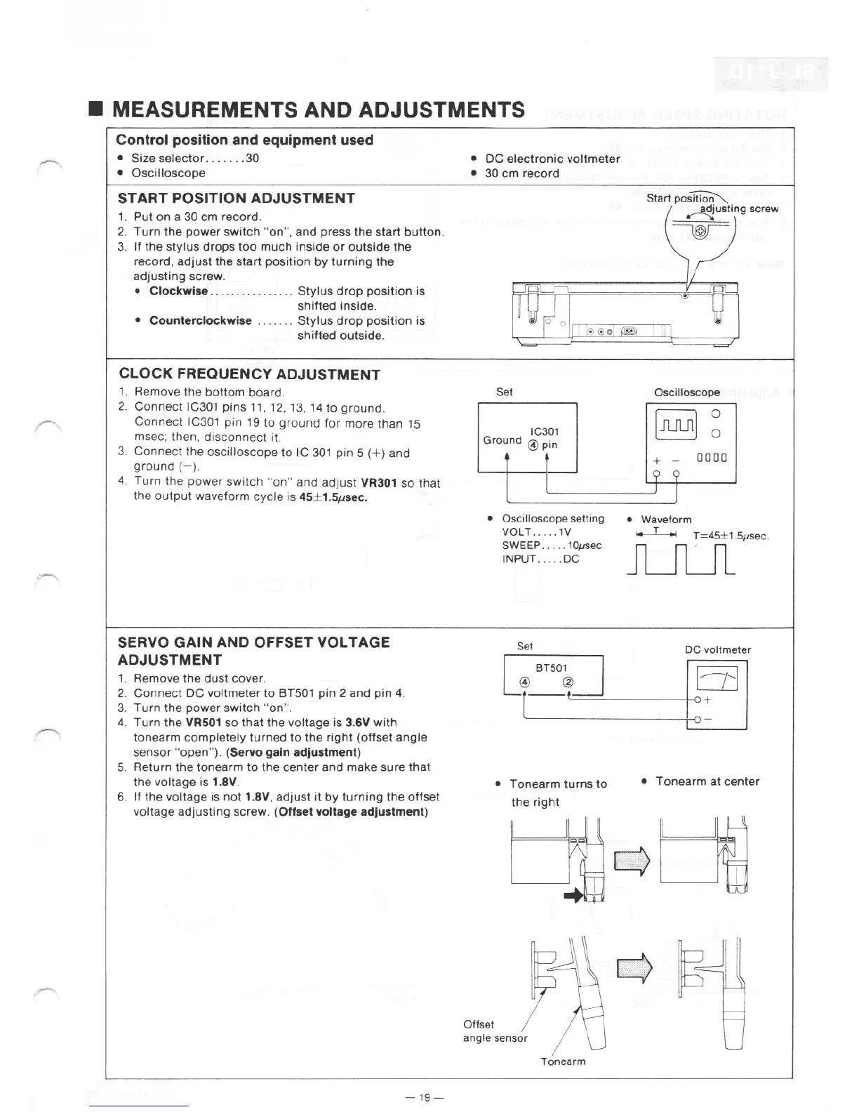
• MEASUREMENTS AND ADJUSTMENTS
Control position and equipment used
•
Size
selector
....
.
..
30
•
Oscilloscope
START POSITION ADJUSTMENT
1.
Put
on
a
30
cm record.
2.
Turn
the
power
switch
"on'', and press
the
start
button.
3.
If
the
stylus
drops
too
much
inside
or
outside
the
record,
adjust
the
start
position
by
turning
the
adjusting
screw
.
• Clockwise
................
Stylus
drop
position
is
shifted
inside.
• Counterclockwise
.....
..
Stylus
drop
position
is
shi
ft
ed
outside
.
CLOCK FREQUENCY ADJUSTMENT
1.
Remove
the
bottom
board
.
2.
Connect
IC301
pins
11
, 12,
13,
14
to
ground
.
Connect
IC301
pin
19
to
gr
ound
for
more
than 15
msec; then, di
sconnect
it.
3.
Connect
the
oscilloscope
to
IC
301
pin
5
(+)
and
ground
(
-)
.
4.
Turn
the
powe
r
sw
i
tch
"on"
and
adjust
VR301
so
that
the
output
waveform
cyc
le is 45± 1.S
µs
ec.
SERVO GAIN AND OFFSET VOLTAGE
ADJUSTMENT
1.
Remove the
dust
cover
.
2.
Connect
DC
voltmeter
to
BT501
pin
2 and pin 4.
3.
Turn
the
power
switch
"on"
.
4.
Turn
the
VR501 so
that
the
voltage
is 3
.6
V
with
tonearm
completely
turned
to
the
right
(offset
angle
sensor
"open")
. (Servo gain adjustment)
5. Return
the
tonearm
to
the
center
and
make
sure
that
the
voltage
is 1.
8V
.
6.
If
the
voltage
is
not
1.SV.
adjust
it
by
turning
the
offset
voltage
adjusting
screw
. (Offset voltage adjustment)
- 1
9-
•
DC
electronic
voltmeter
• 30
cm
record
Start
po~
~usting
screw
~
Set Oscilloscope
0
IC301
Ground
@pin
~
0
+ -
0000
<(
<(
I
J
• Oscilloscope setting • Waveform
Offset
VOLT · ·
···
1V
~
T=45
±
1.
5µsec.
SWEEP
....
. 10µsec.
JUUl
INPUT .
.. ..
DC
Set
DC
voltmeter
Lr_::~J
!?I
•
Tonearm
turns
to
•
Tonearm
at
center
the
right
r-f,\
6-y'
angle sensor
Tonearm