•GENERAL
Power supply:
For
U.S.A.
and Canada:
Dimensions
(W
XHXD
):
315
X
88
X
315
mm
(
12-1/2"X3-1/2"X12-1/2")
We
ight: 3.3 kg (7.4
lb.)
AC
120V
,
60
Hz
For
United
Kingdom
·
AC
240V
.
50
Hz
For
Continental
Europe:
AC
220V
.
50
Hz
aw
Spec1f1cations are subject to change
without
notice
for
further
improvement.
Power consumption:
Weight
and dimensions
shown
are approximate.
•CONTENTS
9'ge
Page
SAFETY PRECAUTION
.
.....
...
.
................
.
..
......
..
..
.. 2
CIRCUIT
BOARD
AND
WIRING
LO
C
ATION
OF CONTROLS
..
. ..
..............
.
.......
..
..
....
. 3
CONNECTION
DIAGRAM
.....................
.
.......
. .. . 14
DISASSEMBLY INSTRUCTIONS
.....
..
.•
..
....•..
.....
....
.
4- 8
BLOCK
DIAGRAM
. . . .
..
. . . . . . . . . . . . .
..
. . . . . . . . . . . . .
..
.....
9,
10
DESCRIPTION OF SVILC6526CPC
.......
• . .
....
.•.
..
....
10
SCHEMATIC
DIAGRAM
.................
.
...
..
......
.....
11
,
12
POWER
SOURCE
CIRCUIT
...
•
......
•
..
..•
.
..
.•
..
. . •
.........
13
EXPLODED
VIEW
...............................
.
.....
.
....
15, 16
REPLACEMENT
PARTS
LIST
.............
.
.......
.
.......
17, 18
MEASUREMENTS
AND
ADJUSTMENTS
..............
•
....
•.•
..............
•
....
19,
20
•
SAFETY PRE
CA
UTI 0
N
(This
"safety
precaution
"'
is
applied
only
in
U.S.A.)
1.
Bef
ore
servicing,
unplug
the power
cord
to
prevent
an
electric shock.
2.
When replacing parts.
use
only
manufacturer's recommended components
for
sarety.
3.
Check
the
cond
it
ion
of
the
power cord. Replace
if
wear
or
damage
is
evident.
4.
After
servicing,
be
sure to restore
the
l
ead
dress, insul
ation
barriers, insulation papers,
shields,
etc.
5.
Before
returning
th
e serviced equipment
to
the customer, be sure
to
make
the
following
insulation resistance test to
prevent
the
customer
from
being exposed
to
a
sh
ock hazard.
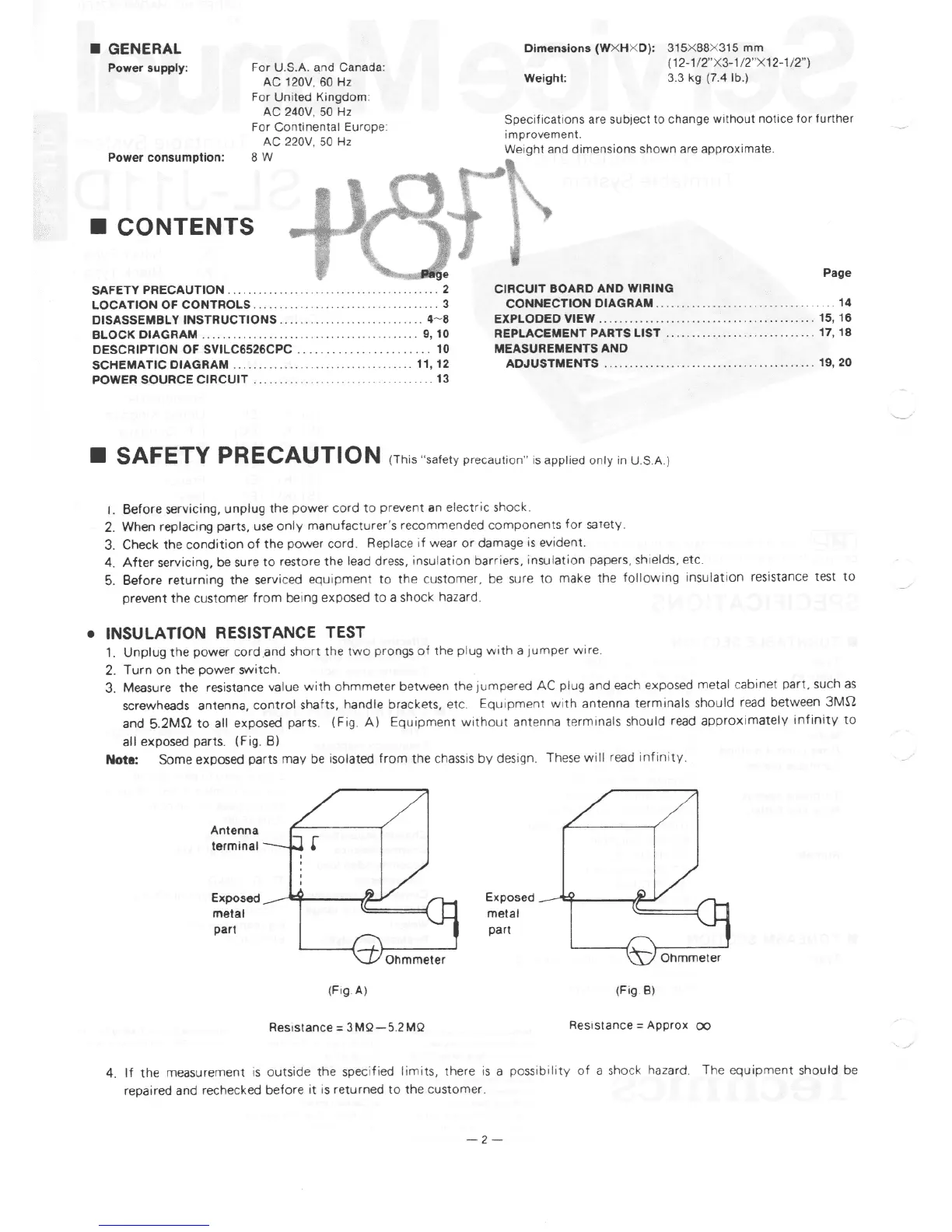
• INSULATION RESISTANCE TEST
1.
Unplug
the
power cord and short
the
two
prongs
of
the
plug
with
a 1umper wire.
2.
Turn
on
the
power switch.
3.
Meas
ure the resistance
value
with
ohmmete
r between
the
iumpered AC plug
and each exposed metal
cabinet
part.
such
as
screwheads antenna,
control
shafts,
handle
brackets, etc.
Equipment
with
antenna terminals should
read between
3Mr2
and
5.2Mr2
to
all
exposed parts. (Fig.
A)
Equipment
without
antenna termina
ls
should
read
approximate
ly
infinity
to
all
exposed parts. (Fig.
Bl
Note: Some exposed parts may be isolated
from
the
chassis
by
design. These w
ill
read
infinity
.
Antenna
terminal
Exposed
metal
part
Ohmmete
r
(Fig.A)
Resistance=
3 MQ- 5.
2MQ
Exposed
-
.....:;~---~-
metal
part
Ohmmeter
(
Fig
.BJ
Resistance=
Approx
oo
4.
If
the measurement
is
outside
the
specified
limits,
there
is
a
possibility
of
a shock hazard. The equipment should be
repaired and rechecked before
it
1s
returned
to th
e customer.
-2
-