tecn@ SALDATRICI ART. 3401 - 3406 - 3407 - 3408 WELDERS ITEM 3401 - 3406 - 3407 - 3408
Documento numero / Document number: MAN1063 Edizione / Edition: Settembre / September 1997 PAG. 16 / 32
La funzione di compensazione interviene controllando la
corrente di saldatura tramite una apposita bobina posta
all'interno del circuito secondario.
Finchè la corrente non supera una soglia prestabilita, il tempo
di saldatura viene automaticamente allungato fino ad un limite
di 99 periodi. Ciò consente di eseguire saldature con un tempo
reale di passaggio di corrente sempre costante.
La soglia di corrente viene regolata, tramite un trimmer, dal
costruttore della saldatrice. Il valore normalmente impostato è
di 1500÷2000A. Il jumper JP1, posto sulla scheda, consente di
disabilitare questa funzione.
COMPENSAZIONE JUMPER JP1
ABILITATA APERTO
DISABILITATA CHIUSO
4.4 CALCOLO CADENZA MASSIMA DI LAVORO
E’ necessario verificare, prima di iniziare la lavorazione, che il
ritmo di lavoro non ecceda quello massimo consentito dalla
macchina per le condizioni di saldatura impostate (tempo e
corrente), provocando un eccessivo surriscaldamento.
Per effettuare questa verifica è necessario conoscere la
corrente di saldatura utilizzata che deve essere misurata
tramite un adeguato amperometro di saldatura.
Il massimo ritmo di lavoro ottenibile dalla macchina è funzione
del carico termico applicato alla macchina stessa, che dipende
dal tempo, dalla corrente di saldatura utilizzati e dal numero di
saldature per unità di tempo. Con questi diversi parametri si
definisce il valore di I
th
ovvero la “corrente termica equivalente
al fattore di marcia del 100%”. Il suo valore si calcola nel
seguente modo:
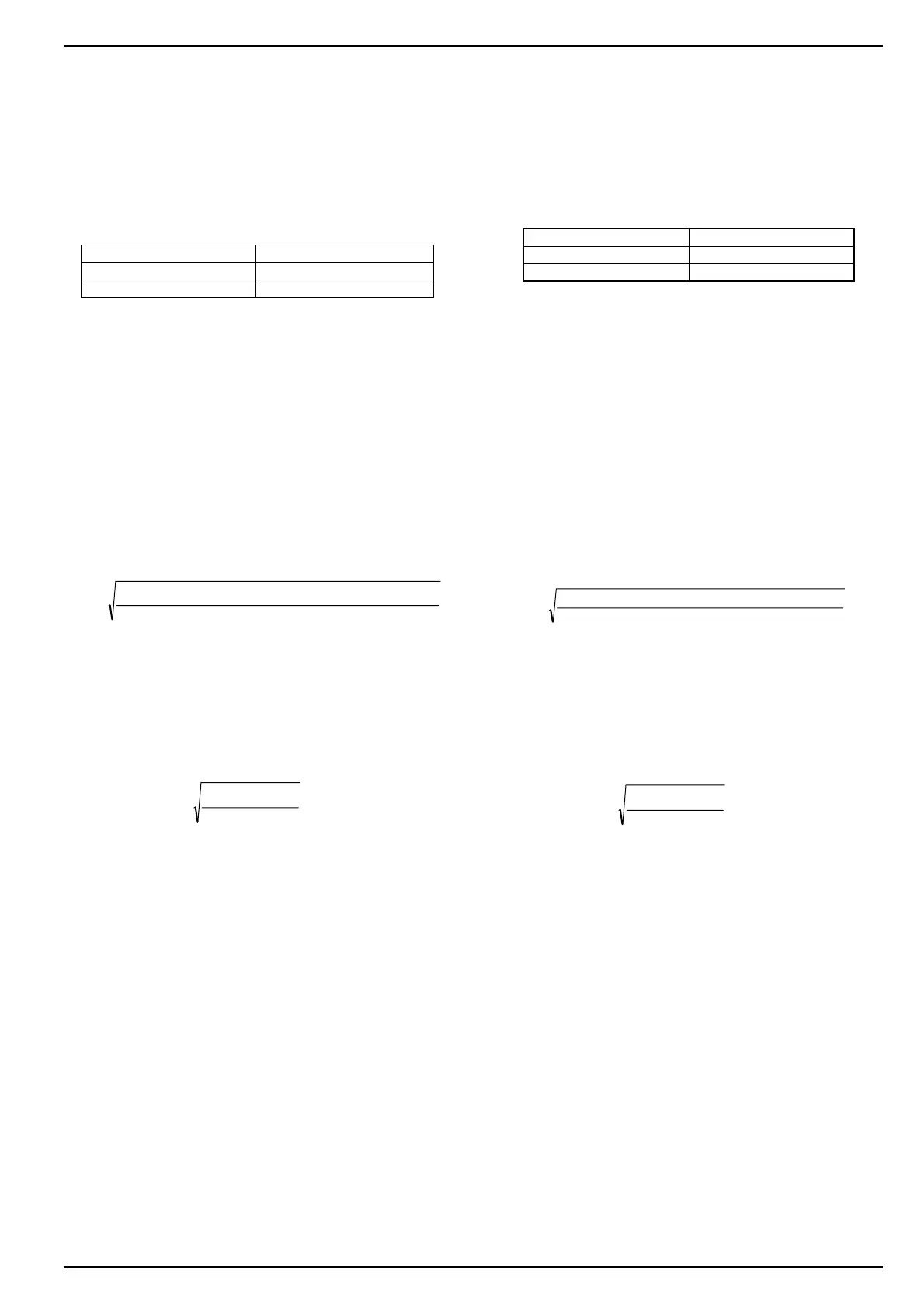
()
I
th
cicli di saldatura al minuto corrente di saldatura in kA
=
×
2
3000
Il valore ottenuto deve risultare inferiore a quello massimo
della saldatrice che è riportato nel paragrafo
“Caratteristiche Tecniche”. In caso contrario è necessario
ridurre il ritmo di lavoro.
Esempio:
Corrente di saldatura = 8000 A, tempo di saldatura = 18
periodi, 5 saldature al minuto.
()()
I
th
=
××
=
18 5 8000
2
3000
A1385
NOTA: Le formule sopra riportate sono valide per le linee di
alimentazione a 50Hz. Per le linee a 60 Hz sostituire il valore
“3000” con “3600”.
The compensation function controls the welding current by
means of a coil located inside the secondary circuit.
Until the welding current does not exceed a pre-set limit, the
welding time is automatically extended up to a limit of 99
cycles. In this way it is possible to carry out welding processes
with an always constant real time of current flow.
The current limit is adjusted, by means of an internal trimmer,
by the welder manufacturer. The standard value is usually
about 1500÷2000 A. By means of JP1 jumper, located on the
card, it is possible to disable this function:
COMPENSATION JUMPER JP1
ON OPEN
OFF CLOSED
4.4 CALCULATION OF THE MAXIMUM WELDING RATING
Before starting the production, it is necessary to check that the
welding rating does not exceed the maximum welding rating
allowed by the welder in comparison with the set welding
conditions (time and current), otherwise causing a too high
over heating.
To carry out this test, it is necessary to know the used welding
current which must be measured with an adequate welding
ammeter.
The welder maximum welding rating is the function of the
thermal load applied to the welder itself, depending from both
the used time and welding current and from the numbers of
welds for unit of time. With these different parameters it is
possible to define the I
th
value, that is the “equivalent thermal
current at the duty cycle of 100%”. Its value is calculated as
follows:
I
th
=
welding cycles per minute x (welding current in kA)
3000
2
The resulting value must be lower than the welder
maximum one; this value is stated on the “Technical
Features” paragraph. On the contrary, it is necessary to
reduce the welding rate.
Example:
Welding current = 8000 A, welding time = 18 periods, 5 welds
per minute.
()()
I
th
=
××
=
18 5 8000
2
3000
A1385
NOTE: Above formulas are for 50Hz supply lines. For 60Hz
supply lines exchange the “3000” value with “3600”.
 Loading...