tecn@ SALDATRICI ART. 3401 - 3406 - 3407 - 3408 WELDERS ITEM 3401 - 3406 - 3407 - 3408
Documento numero / Document number: MAN1063 Edizione / Edition: Settembre / September 1997 PAG. 15 / 32
4.2 REGOLAZIONE FORZA AGLI ELETTRODI
La scelta della forza di saldatura va fatta, basandosi su tabelle
od esperienza personale, in relazione allo spessore delle
lamiere da saldare, alla qualità del punto desiderata ecc.
La regolazione va sempre eseguita con il
controllo di saldatura regolato in modalità “NON
SALDA” per evitare situazioni di pericolo dovute
ad una errata regolazione. Eseguire sempre delle
prove di ciclo in “NON SALDA” prima di iniziare la
produzione.
Una forza agli elettrodi eccessiva può provocare:
• Eccessive impronte della saldatura.
• Possibile breve durata degli elettrodi.
• Saldature deboli o non avvenute a causa della riduzione
della resistenza di contatto che permette il passaggio della
corrente senza portare il pezzo alla temperatura di fusione.
Una forza agli elettrodi insufficiente può provocare:
• Spruzzi di materiale fuso.
• Incollatura dei pezzi sull'elettrodo.
• Saldature con una superficie esterna poco gradevole.
La forza agli elettrodi si regola agendo sulla vite 10513 che
carica più o meno un molla. Non è possibile determinare la
forza agli elettrodi a meno che non si disponga di un
dinamometro. In mancanza di questo la regolazione può
essere effettuata a tentativi eseguendo delle prove sui pezzi di
materiale simile a quello che deve essere saldato.
4.3 REGOLAZIONE DEL PROGRAMMA DI LAVORO
Questa operazione consiste nello scegliere i valori di tempo e
corrente di saldatura da impostare sul controllo tramite le due
apposite manopole.
La scelta dei parametri va fatta, basandosi su tabelle od
esperienza personale, in relazione allo spessore delle lamiere
da saldare, alla qualità della saldatura desiderata ecc.
Si consiglia di utilizzare tempi di saldatura corti che riducono il
riscaldamento degli elettrodi aumentandone la durata ed
evitandone l'ossidazione nella parte di contatto.
Le saldature di maggiore qualità si ottengono utilizzando tempi
di saldatura più corti possibili e con corrente e forza agli
elettrodi elevati.
Si fa notare che in caso di saldatura di spessori diversi fra loro
i parametri di saldatura da utilizzare sono quelli che si
riferiscono allo spessore minore.
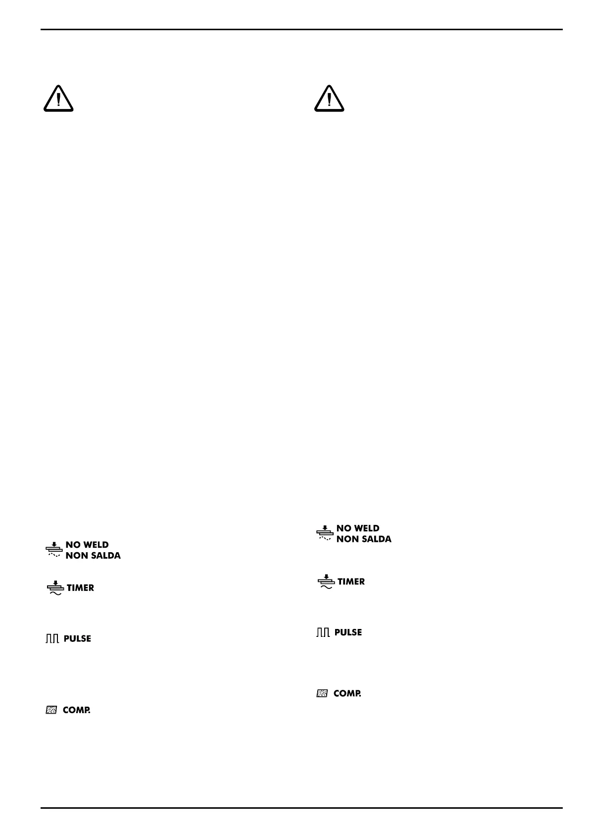
Il selettore MODE consente di selezionare 4 modalità
operative:
La saldatura è disabilitata, questa
modalità si utilizza per effettuare delle
prove senza corrente di saldatura.
Questa è la normale modalità di
funzionamento. La saldatrice esegue la
saldatura erogando la corrente regolata con la manopola
CORRENTE per il tempo impostato con la manopola TEMPO.
In questa modalità la saldatrice effettua le
saldature erogando la corrente ad impulsi.
Questa funzione è utile nella saldatura di grossi spessori e di
lamiera ad alto limite di snervamento. Quando si utilizzano le
pulsazioni i tempi di saldatura necessari devono essere
leggermente aumentati.
Selezionando questa modalità la saldatrice
esegue le saldature attivando la funzione di
compensazione della corrente secondaria. Questa modalità è
utilizzata per facilitare la saldatura di lamiere e tondini con
tracce di ruggine. L’ossidazione dei pezzi impedisce il
passaggio di corrente durante la prima fase della saldatura e
riduce così, in maniera variabile da saldatura a saldatura, il
tempo reale di passaggio di corrente.
4.2 ELECTRODE FORCE ADJUSTMENT
The welding force must be selected taking into consideration
both tables and personal experience, and in relation to the
sheets thickness, the desired spot quality, etc.
Always adjust by keeping the welding control
unit on “NO WELD” in order to avoid any risk
caused by a wrong adjustment. Always carry out
“NO WELD” cycle tests before starting the
welding process.
An excessive electrodes force can cause:
• welding over marks;
• possible electrodes short life;
• weak welding or false welding due to a reduction of the
contact resistance, which allows the current to pass through
without bringing the piece to the melting temperature.
An insufficient force on electrodes can cause:
• spatters of melted material;
• stuck weld of the pieces on the electrode;
• welding with a disagreeable outside surface.
The electrode force is adjusted by operating on screw 10513,
which alters the load on a spring. The electrode force cannot
be measured unless one has a dynamometer. If this is not the
case, the adjustment has to be made by trail and error,
effecting test welds on material similar to that one to be
welded.
4.3 WORKING PROGRAM ADJUSTMENT
This operation enables to choose the parameters of time and
welding current to be entered on the welding control by means
of two knobs.
Select the parameters from either tables or personal
experience, taking into consideration the plate thickness, the
welding desired quality etc.
We suggest to use short welding times to reduce the
electrodes heating, thus increasing their life, at the same time
avoiding oxidation on the contact surfaces. The best quality
welds are obtained by using times as short as possible with
high current and high electrode force. Notice that when
operating pieces with different thickness, the welding
parameters to be used are those which refer to the lower
thickness.
The MODE selector enables to select 4 different operative
procedures:
The welding is disconnected; this
procedure is used to carry out some
tests without circulation of welding
current.
This is the standard working procedure. The
welder carries out the welds supplying the
current adjusted by means of the knob CURRENT for the
period of time set by means of the knob TIME.
By setting this procedure, the welder carries out
the welds supplying the current by pulses. This
function is useful to weld very thick materials and high-limited
yield sheets. When using the pulses, the necessary welding
times must be slightly increased.
By selecting this procedure, the welder carries
out the welds activating the compensation
function of secondary current. The compensation function of
secondary current is used to facilitate the welding process of
oxidised sheets and rods. The pieces oxidation blocks the
current flow during the first welding phase, thus limiting, in a
different way depending from the welding process, the real
time of current flow.
 Loading...