English
4
BLAST CHILLER ISTRUCTION ST
2.6 REFRIGERATION COMPONENT CONNECTIONS
REMOTE ASSEMBLIES
Appliance power lines are sized for installation distances of
up to 10 metres. For greater distances, seek advice from.
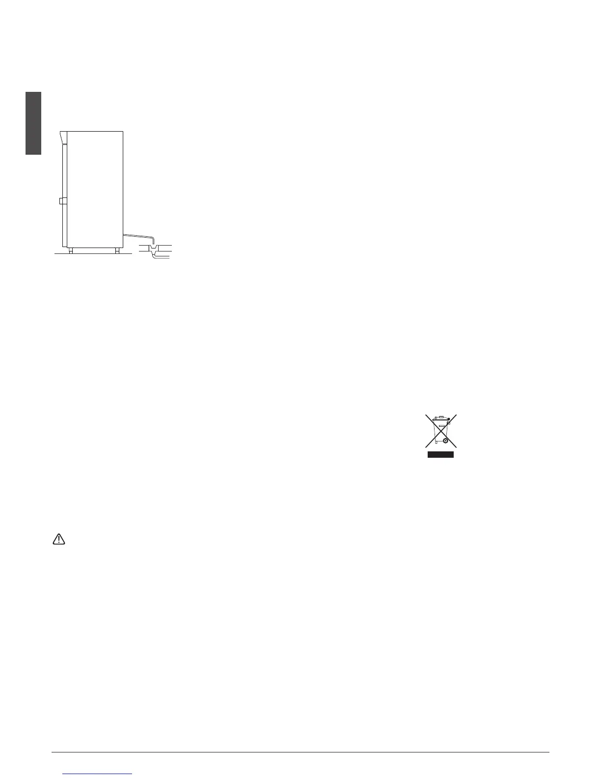
2.7 CONDENSATE DRAINAGE CONNECTION
Fit a condensate/wash water drainage hose with a minimum
diameter of 1” (“Geberit” or similar type).
Provide a waste pipe with a
trap with a diameter of at least
1 1/2” at floor level.
2.8 INFORMATION FOR THE INSTALLATION TECHNICIAN
Before starting up the machine, check that it has been cor-
rectly installed and commissioned (test report).
1. Check that there are no gas leaks from weldings or joints
made during installation works.
2. Check that the pipes connecting the condenser to the re-
mote condensing unit have been well insulated.
3. Check all wiring connections.
4. Check electrical input.
5. Check the standard pressure in the refrigerant system.
6. Check the water connections and efficiency of the pressure
switch valve during operation, as well as the flow of conden-
sing water (in water-cooled units).
7. Perform at least one blast freezing cycle (to the SET tempe-
rature) and one manual defrosting cycle.
In the event that the appliance or the remote condensing
unit have not been transported in a vertical position (e.g. on
the back) or have been overturned during installation works,
allow at least 4 hours before starting up the equipment.
• Inform the customer of the exact purpose of the appliance,
with specific reference to the use and requirements of the
customer.
The appliance must be installed and put into service by a
technician authorised.
2.9 SAFETY AND CONTROL SYSTEMS
• Door microswitch:
shuts down fan operation in the cell when the door is ope-
ned.
• General fuses:
protect the power circuit against short circuiting and over-
loads.
• Compressor heat relay:
intervenes in the event of overloads or operating faults.
• Safety pressure switch:
intervenes in the event of excessive pressure in the refrige-
rant circuit.
• Plug fuses:
intervene in the event of overpressure or operating fault in
the safety pressure switch (see above).
• Chamber temperature control:
operated by the electronic board by means of a probe inside
the cell.
• Temperature control end defrost cycle:
controlled by the electronic board by means of the probe in
the evaporator.
2.10 DISPOSAL OF WASTE ELECTRONIC AND ELECTRICAL
EQUIPMENT (WEEE)
The following information regards member states of
the EU. The crossed-out litter bin symbol indicates
that the product cannot be disposed of as residential
waste. Ensuring that this product is disposed of
correctly will help prevent potential negative effects
on the environment and to human heath that could be
caused if disposed of in an incorrect manner.