45
Instruction and maintenance manual
ENGLISH
4.3.2 Power cable
TECNOMAGNETE supplies a suitable multi-pole
power cable with a standard length of four meters,
which prevents overheating problems and a voltage
drop within the rating of the TECNOMAGNETE mod-
ule, if used in ordinary operating conditions.
Before using longer cables, always make sure that
the cable section used guarantees a voltage drop
below 1%.
Ordinary operating conditions are intended as inter-
mittent working cycles, with intervals of at least one
minute between two enabling cycles.
4.3.3 Selecting the correct dimensions for dis-
charge cables
The discharge cable tted on ST200 comprises four
leads suitable for the purpose, has a standard length
of six meters and is dimensioned to prevent over-
heating and the loss of power on the chuck in ordi-
nary operating conditions.
Ordinary operating conditions are intended as ena-
bling/disabling cycles occurring at an interval above
1 minute.
Before using longer cables, always make sure that
the cable section used guarantees a voltage drop
below 1%.
4.3.4 Electric specifications
All ST200 controllers are available as single and two-
phase models; the maximum installed power for
each cycle is 25 kVA (cosϕ=0.9) for two-phase 400V
plants, 15kVA for 230V plants and 32 kVA for 480V
plants.
To optimally protect the installation, it is necessary to
install a suitable magnetothermal switch (curve C)
with an I
n
value compliant with the rating specied
on the nameplate.
5
ENABLING
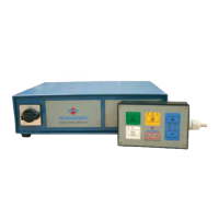
5.1 ST100
ST100 controllers are not tted with a specic ena-
bling device, which may however be ordered as op-
tional (see Chapter 6.1).
5.2 ST200
The ST200 controller has an enabling device tted
on connector DB9 situated on the rear of the control-
ler (PINS 8 and 9).
The technical specications for the contact are:
•
Voltage 30V, current 1A
•
Voltage 110V, current 0.3A
It is always advisable to use an auxiliary relay.
Before using other models of start systems, contact
TECNOMAGNETE S.p.A. for assistance.
When at least one of the magnetic chucks controlled
by ST200 is in magnetization mode, the enabling
contact is closed. PINS 6 and 7 can be connected to
the power of the tool machine and used to run the
enabling cycles through the controller: the controller
can only run the cycles when PINS 6 and 7 are clo-
sed. Connect the safety catch to the operating ma-
chine on which the TECNOMAGNETE module is in-
stalled.
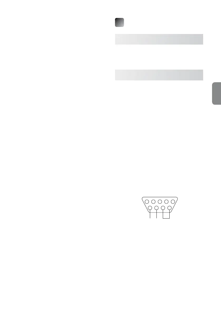
DB9 PIN connector
5 4 3 2 1
9 8 7 6
ENABLE ENABLE
MACHINE CONTROLLER
pin n° 1 ➜ B1
pin n° 2 ➜ A2
pin n° 3 ➜ Vdc
pin n° 4 ➜ Gnd
pin n° 5 ➜ Alarm
pin n° 6 ➜ COM ENABLE Controller
pin n° 7 ➜ ENABLE Controller
pin n° 8 ➜ COM ENABLE machine
pin n° 9 ➜ ENABLE machine
When possible, it is advisable to use both types of
contacts.