37
Instruction and maintenance manual
ENGLISH
3
DESCRIPTION
OF THE SYSTEM
3.1 Description of the controllers
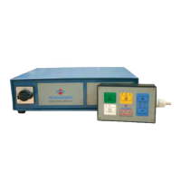
ST is an innovative electronic controller for
networked chucks designed for milling and grin-
ding operations.
The sections that follow provide information on the
size and the basic characteristics of the available
models:
•
ST100F (milling)
•
ST100R (grinding)
•
ST200F (milling)
•
ST200R (grinding)
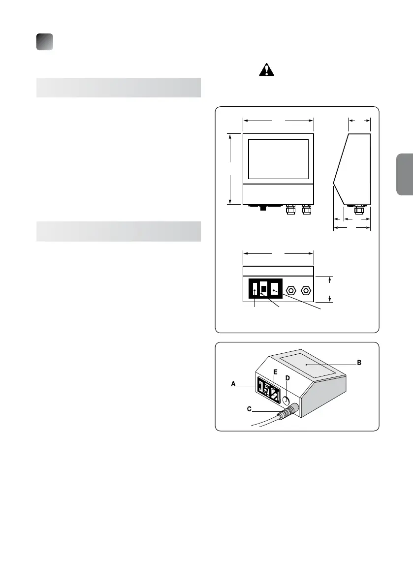
3.2 Model ST100X
The rated operating voltage is 230V.
The control push-button panel is integrated in to the
controller.
The control electronics are situated under the control
push-button panel and enclosed in a plastic hou-
sing.
To simplify installation and facilitate the reading of
the push-button panel, it is also possible to install
the controller on a workbench or mount it on the wall
by simply rotating the control panel.
The plastic material of the housing ensures a high
level of insulation and the utmost safety during use.
The rear part of the controller has a block with a male
pin (designed to be connected to the power cable),
an ON–OFF (0-1) switch and a fuse-holder with two
12.5A protection fuses (type 5x20 mm). Two or more
cable ties for the output of the discharge cables of
the chucks to be magnetized may be present next to
these components.
The maximum useful current that ows into the
ST100X controller is approximately 12.5A; the cur-
rent supplied to the module is impulsive with a cycle
time around a few hundreds of milliseconds (app. 1
second per discharge).
ST100X controllers are suitable to control small
chucks with a single phase voltage of 230V and a
maximum absorption of rated current of 3kW.
For different rated voltages, use a transformer with a
suitable transformation ratio and a rating suitable to
handle the maximum power of the chuck or at any
rate a maximum power of 4kVA. For example, if the
available voltage is 400V, a transformer with a
400/230 transformation ratio is required.
ATTENTION!
Control units can be moved only
when controls are not powered.
135
135
40
50
75
135
40
MAIN PARTS
A ➜ Main switch
B ➜ Push-button panel
C ➜ Discharge cable output
D ➜ Start contact
E ➜ Power supply input
Fuse-holder Main Power supply
switch input
Rear