13
2-1-4 Motor Terminal Layout
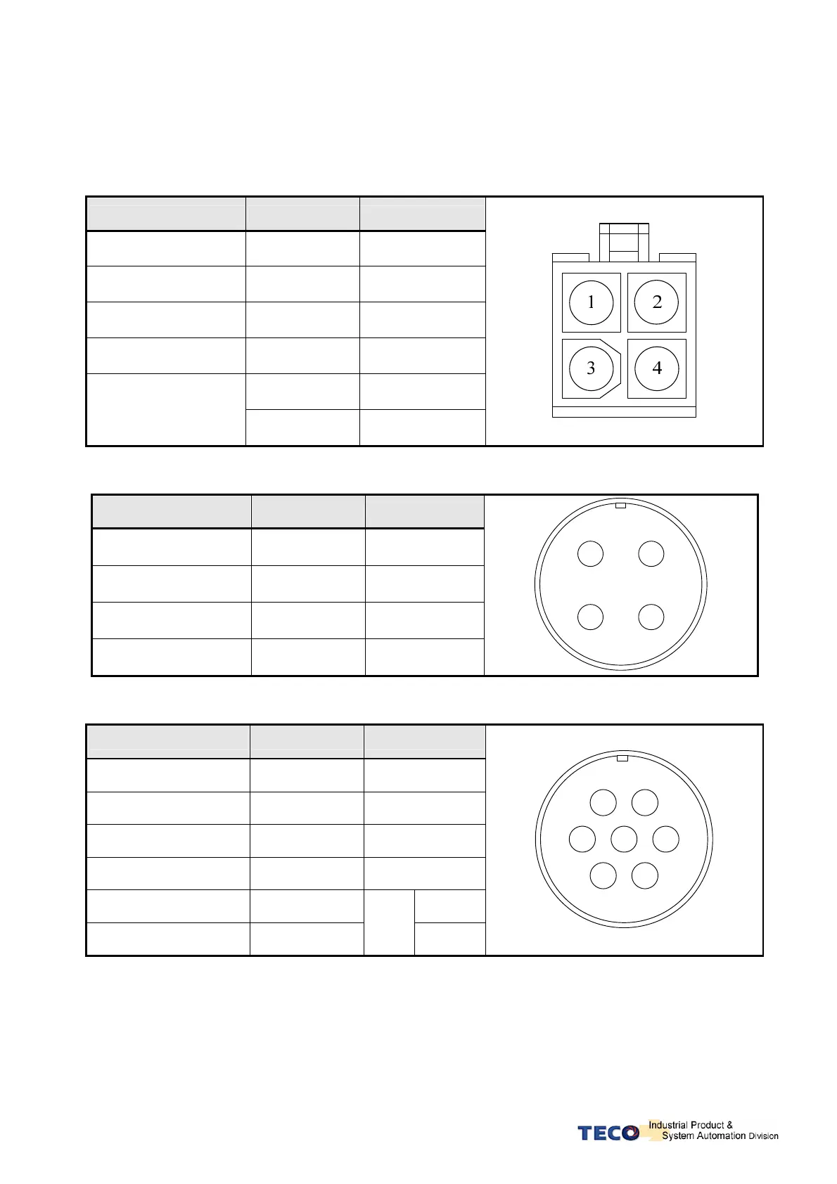
A Table of Motor-Terminal Wiring
(1) General Joint:
Terminal Symbol Color Signal
1 Red U
2 White V
3 Black W
4 Green FG
Fine red DC +24V
Brake control wire
Fine yellow 0V
(2) Military Specifications Joint (No Brake):
Terminal Color Signal
A Red U
B White V
C Black W
D Green FG
A
B
D
C
(3) Military Specifications Joint (Brake):
Terminal Color Signal
B Red U
G White V
E Black W
C Green FG
A Fine red DC +24V
F Fine yellow
BK
wire
0V
A
B
D C
E
F
G
P.S.: The military joint with BK of servo motor has 9 Pins; and the encoder joint has also 9 Pins. Please
confirm before wiring.

 Loading...
