Chapter 4 Relay Ladder Logic Programming 72
Example 2: Timer/Counter Preset Value Compare
The Comparator instruction can be used to compare Timer, Counter, and RTC values to a constant value or to
each other. In this example below, Mode 5 is the selected function that compares the value of Counter (C1) to a
constant value (N) of 15 counts (the decimal point is ignored). Status coil G1 turns ON if C1 is to 15 counts.
HMI Display Instructions
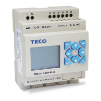
The SG2 smart relay includes a total of 15 HMI
instructions that can be used throughout a program.
Each HMI instruction can be configured to display
information on the SG2 12×4 character LCD in text,
numeric, or bit format for items such as current
value and target value for timers/counters,
Input/Output bit status, RTC (real time clock) and
Analog comparator.
Each HMI instruction is configured separately using
the Edit»HMI/Text menu selection from the SG2
Client software.
In the adjacent example, HMI instruction H1 is
configured to display the value of I1 and T1, and
some descriptive text. Numeric display data
selections are Timer, Counter, RTC, and Analog. Bit
display data selections for “ON” and “OFF”
messages are “I” inputs, “M” internal relays, “X”
expansion inputs and “Z” keypad inputs.
Allows the SEL button on the SG2 keypad to
activate the selected message onto the LCD even
when Hx coil is inactive.

 Loading...