24
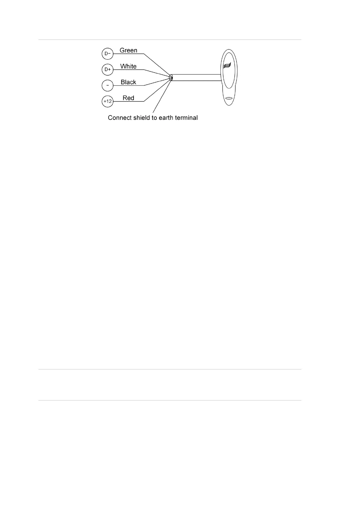
Figure 6: Connecting a Smart Card Reader to the one of the buses
Terminating the RS-485
All RS-485 devices (including the panel) use a 470 Ω RS-485 termination resistor
where required. RS-485 termination resistors are used to set the impedance of
the RS-485 to around 220 Ω in order to minimise noise. The termination resistor
may be external or on-board (devices with an on-board resistor use a link to set
the RS-485 termination to ON).
A RS-485 should have only two devices with the RS-485 termination set to ON
(or the RS-485 termination resistor fitted):
• In a straight RS-485 configuration, the TERM links are ON at the
ChallengerPlus panel and the most distant device.
• In a star RS-485 configuration, the TERM links are ON at the two devices
that are the furthest apart (and OFF at the ChallengerPlus panel).
In a completely connected (but powered down) system, you can check for correct
LAN termination by measuring the resistance across the D+ and D− terminals:
• 0 Ω indicates a short circuit in the cabling
• 160 Ω or less indicates that too many devices are terminated
• 220 Ω is good
• 470 Ω or more indicates that not enough devices are terminated
Lock power
Lock power can only be provided through an external source and not from the
board itself. The wiring details are explained in the next page.
Note: Devices connected to the RS-485 buses and powered by the Network
Access Controller must comply with Appendix B: Output fusing and user current
limits on page 34