25
Door lock relay wiring
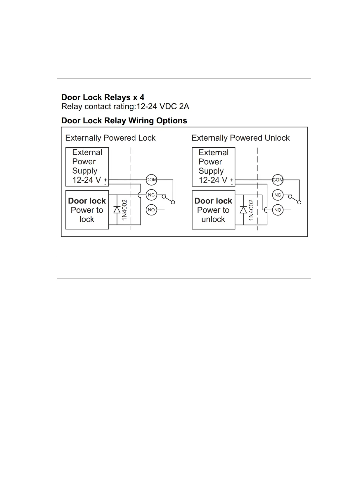
Figure 7 below details the wiring for the relay terminal blocks when the lock
power is externally powered.
Figure 7 Door Lock Relay Wiring Options
Note: A suppression diode such as 1N4004 must be used in door lock circuits.
The diode must be co-located with the lock.
When powering locks from an external power supply or using the relays for other
purposes, the relay contact rating must be observed.
Maximum switching capacity (resistive/load): 3A, 30VDC
Minimum switching capacity: 100mA, 5VDC
Bell Relay
The onboard bell relay can be treated as another relay that can be mapped and
used to activate a door lock, buzzer or siren. Information on using the relay can
be found in the TS1067E Network Access Controller Programming Manual.
Inputs
Inputs can be configured as an alarm input if the Network Access Controller is
connected to a ChallengerPlus system via the LAN.
A Challenger system can receive alarm signals from:
• The Challenger panel’s on-board inputs
• Inputs connected to Data Gathering Panels (DGPs)