26
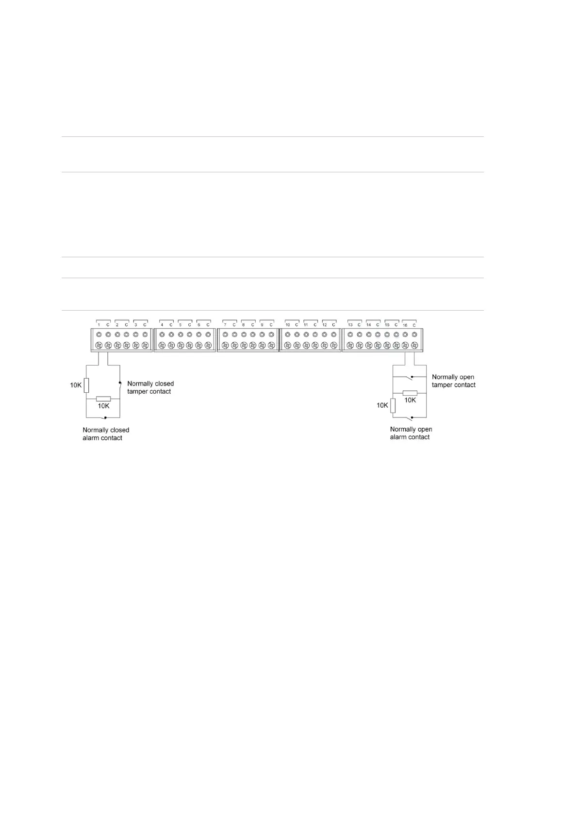
Each pair of input terminals may be connected to a device such as a detector or
reed switch.
The Network Access Controller can monitor its input circuits for four states
(sealed, unsealed, open circuit, and short circuit). This is accomplished by using
two end-of-line (EOL) resistors in each input circuit, as shown in Figure 8 below.
Note: A Network Access Controller can have various EOL resistor values for
input tamper monitoring (the default is 10 kΩ resistors).
Install EOL resistors in input circuits at the end of the circuit.
If an alarm device is connected, place the EOL resistors at the device’s
connections.
If an input is not used, you do not need to connect an EOL resistor.
Tip: Use sleeves on the resistor leads to prevent accidental shorting.
Figure 8: Four-state monitored input circuits
When four-state monitoring is used, the panel uses the circuit’s resistance to
determine the state of the input. In this example, 10 kΩ EOL resistors have been
used:
• 10 kΩ indicates sealed
• 5 kΩ or 20 kΩ indicates unsealed
• Open circuit indicates input tamper
• Short circuit indicates input tamper
To use four-state monitoring, input tamper monitoring must be set to Yes (Install
menu option 7, System Options) for the ChallengerPlus panel, and tamper
monitoring must be enabled for the Network Access Controller. See the TS1067E
Network Access Controller Programming Manual for information on enabling
tamper monitoring.
Alternatively, the ChallengerPlus system can be configured to monitor inputs for
two states (sealed and unsealed). This is accomplished by using one resistor in
each circuit, as shown in Figure 9 on page 27.