6. Operating the system
6.1. Explanation of the operating elements
Control functions, setting options for programs, menu navigation, error messages, etc. are
described in the enclosed operating manual of the unit control. There is also an explanation of the
elements of the control panel.
Operating elements for the device control
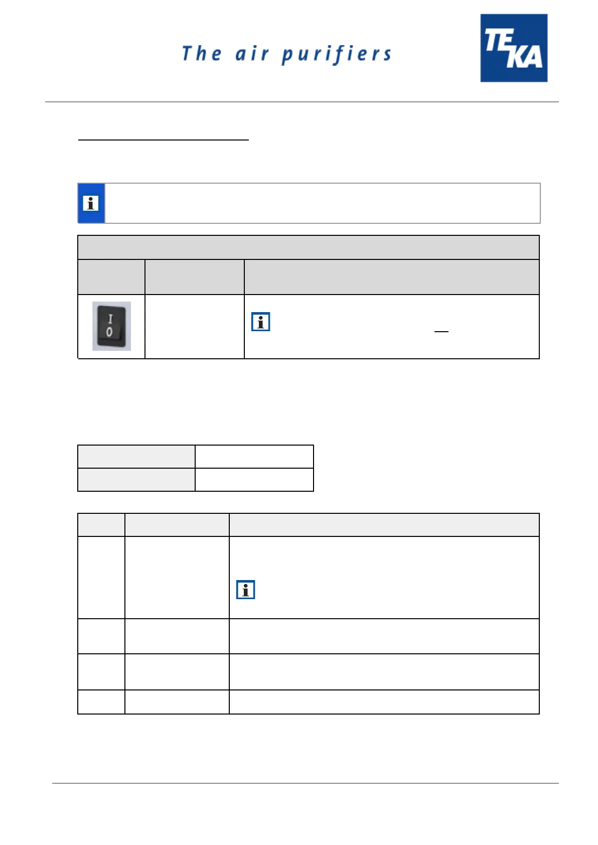
By means of this switch, the device is switched on and off.
When the device is switched off, it is not disconnected from
the power supply.
6.2. Connection of an external control
There is the possibility to control the unit from extern. For this purpose, a connection is provided on the
unit (see chapter 2.1).
In order to switch on the filter unit, a contact has to be connected
between pin 1 and pin 2. The unit is switched out when the contact
is opened.
When the follow-up time is activated, the unit switches off
after the preset period of time.
Pin serves for the evaluation of an fault indication.
(NO: normaly open)
External message
“Operation”
Pin serves for the evaluation of the operational control.
(NO: normaly open)
BA_LFE-101-201-301_220114_EN