© 2016 284_D - 05/16
24 of 60
A Watts Water Technologies Company
N
G
L
L
NG
Ground
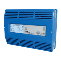
Wiring an Indirect DHW Pump Terminals 85, 86
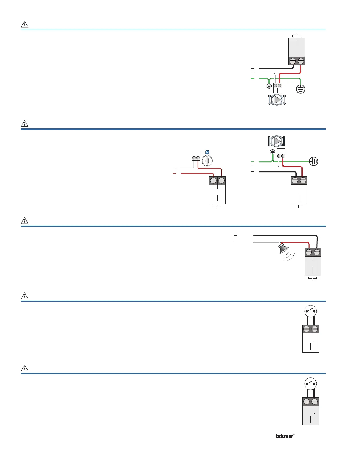
Wiring a Combustion Air (C.A.) Damper / DHW Recirculation Pump Terminals 43, 44
A C.A. damper or DHW recirculation pump requiring up to
230 V (ac) 5 A, 1/6 hp
can be
switched through the Auxiliary terminals.
An indirect DHW pump requiring up to
230 V (ac) 5 A, 1/3 hp
can be switched
through the IDHW Pump terminals.
• Connect the line wire (L) to terminal 85.
• Connect a wire from terminal 86 to the pump L.
• Connect a wire from the pump N back to the power source neutral.
• Ensure grounds are connected in the pump & control wiring chambers.
Pump
IDHW
85 86
Boiler
Control 284
N
G
L
L
N
Auxiliary
43 44
Ground
Boiler
Control 284
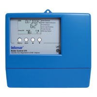
Wiring an Alert Terminals 45, 46
An Alert Device requiring up to 230 V (ac) 5 A, 1/6 hp can be switched through the Alert
terminals to provide notification of specific system events.
• Connect the line wire L (line voltage) or R (low voltage) to terminal 46.
• Connect a wire from terminal 45 to L or R on the alert device.
• Connect the N (line voltage) or C (low voltage) back to the power source neutral.
Flow Proof
1
2
Call
C.A. Proof
Call
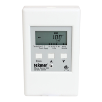
Wiring a Flow Proof Terminals 1, 2
Wiring a Combustion Air (C.A.) Proof Terminals 3, 4
The 284 requires a closed switch or short for proof of flow. Up to 24 V (ac) can be passed through the
switch. If a flow proof device is being used, ensure the External Flow Proof / Off DIP switch on the front
of the control is set to the External Flow Proof position.
• Connect the Flow Proof Call terminals 1 & 2 to the flow proof device.
If a flow sensor is being used as the flow proving device, a jumper must be placed across the
flow proof call terminals.
The 284 requires a closed switch or short for proof of combustion air. Up to 24 V (ac) can be passed
through the switch. If a combustion air proof device is being used, ensure the External C.A. Proof / Off
DIP switch on the front of the control is set to the External C.A. Proof position.
• Connect the C.A. Proof Call terminals 3 & 4 to a combustion air proof.
N or C
Alert
45 46
Boiler
Control 284
Boiler
Control 284
Boiler
Control 284
C
R
R
C
Auxiliary
43 44
• Connect the line wire (L) or R (low voltage) to terminal
43.
•
Connect a wire from terminal 44 to the L or R on the
auxiliary device.
• Connect the N (line voltage) or C (low voltage) back to
the power source neutral.
• Ensure grounds are connected in the pump & control
wiring chambers.
C.A.
Damper
DHW
Recirculation
Pump