C
LEAR
P
ATH
-SC
U
SER
M
ANUAL
R
EV
.
1.36
10
T
EKNIC
,
I
NC
. T
EL
.
(585)
784-7454
2.
I
NSTALL THE
SC
H
UB
"E
ND
-O
F
-L
OOP
"
J
UMPER
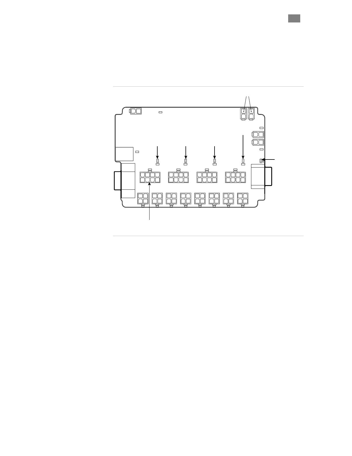
Place one (and only one) jumper block on the 2-pin header associated
with the last motor connected to your SC Hub. Motors must be populated
in order from CP0 to CP3 (do not skip motor locations or the system will
not communicate properly). Place the jumper on J0 for a single motor, on
J1 for two motors, and so forth. See the diagram below for details.
CP3
0A 1A
1B 2B 3A
CP0
OPEN
CP2
CP1
0B 2A
3B
+ 24V -
GLOBAL STOP
First motor always
connects here
DATA
DB9R-M
DB9R-F
24V Input
J0 J1 J2 J3
J5
Place one jumper per SC Hub only!
Place jumper
here for one
motor
Place jumper
here for two
motors
Place jumper
here for three
motors
Place jumper
here for four
motors
Place jumper
here if you add
another SC Hub
(5 or more motors)
SC4-HUB jumper placement
Note: If you connect a second SC Hub, place one jumper at J5 on the first
SC Hub. Then, on the second SC Hub, place one jumper at the last
populated motor location.
 Loading...