Specification-2465 Operators
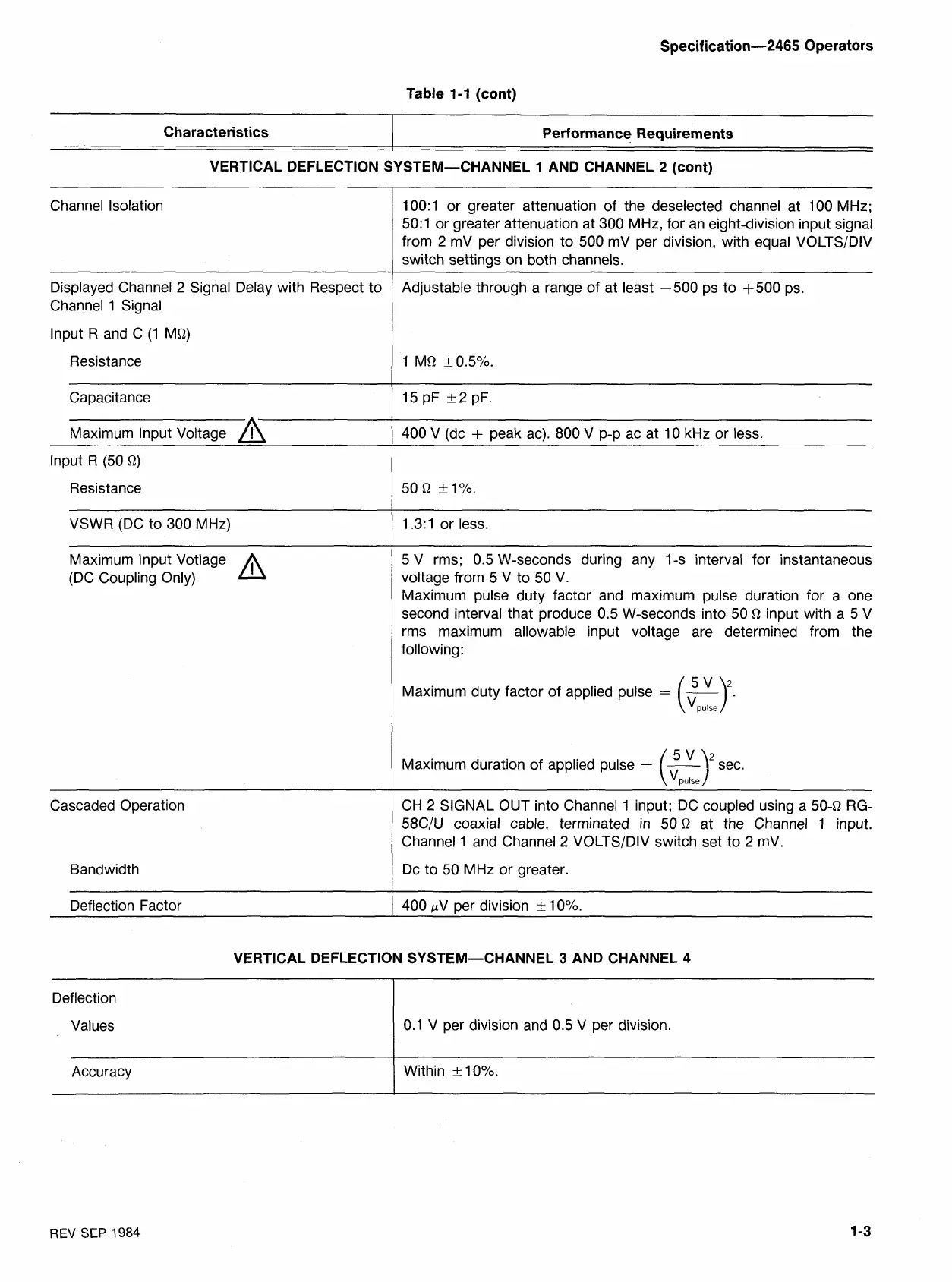
Channel Isolation
Table
1-1
(cont)
Displayed Channel
2
Signal Delay with Respect to
Channel
1
Signal
Characteristics
lnput R and C
(1
MQ)
Performance Requirements
Resistance
VERTICAL DEFLECTION SYSTEM-CHANNEL
1
AND CHANNEL
2
(cont)
Capacitance
Maximum lnput Voltage
A
lnput
R
(50
Q)
Resistance
VSWR (DC to
300
MHz)
Maximum lnput Votlage
(DC Coupling Only)
A
Cascaded Operation
Bandwidth
Deflection Factor
100:l
or greater attenuation of the deselected channel at
100
MHz;
50:1
or greater attenuation at
300
MHz, for an eight-division input signal
from
2
mV per division to
500
mV per division, with equal VOLTS/DIV
switch settings on both channels.
Adjustable through a range of at least
-500
ps to
+500
ps.
400
V (dc
+
peak ac).
800
V
p-p ac at
10
kHz or less.
1.3: 1
or less.
5
V rms;
0.5
W-seconds during any 1-s interval for instantaneous
voltage from
5
V to
50
V.
Maximum pulse duty factor and maximum pulse duration for a one
second interval that produce
0.5
W-seconds into
50
Q
input with a
5
V
rms maximum allowable input voltage are determined from the
following:
Maximum duty factor of applied pulse
=
-
(
:p:l-
Maximum duration of applied pulse
=
(57
sec.
V,u,se
CH
2
SIGNAL OUT into Channel
1
input; DC coupled using a
504
RG-
58C/U
coaxial cable, terminated in
50
Q
at the Channel
1
input.
Channel
1
and Channel
2
VOLTS/DIV switch set to
2
mV.
Dc to
50
MHz or greater
400
pV per division
2
10%.
VERTICAL DEFLECTION SYSTEM-CHANNEL
3
AND CHANNEL
4
Deflection
Values
REV
SEP
1984
0.1
V per division and
0.5
V per division.
Accuracy
Within
-t-
10%.