Specification-2465 Operators
Table
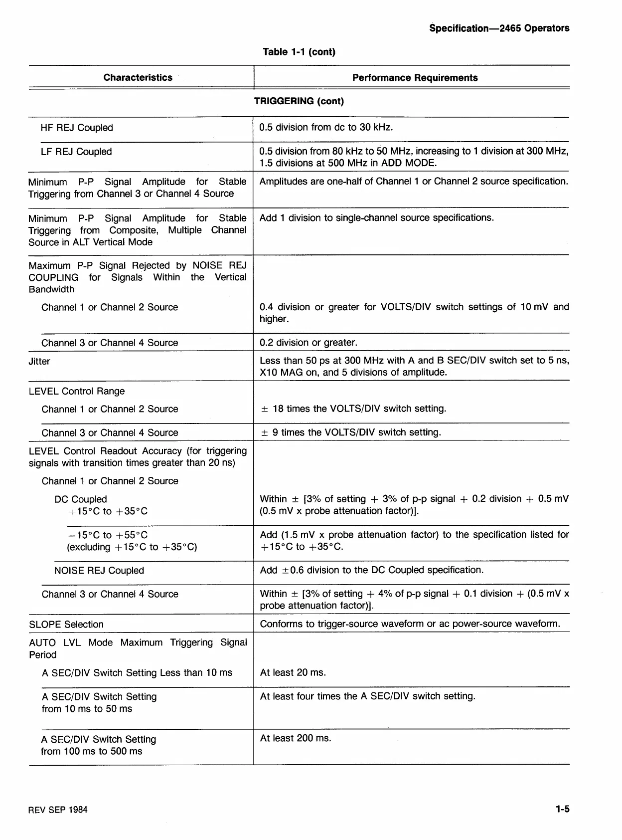
1-1
(cont)
Characteristics
I
Performance Requirements
TRIGGERING (cont)
0.5 division from dc to 30 kHz.
HF REJ Coupled
LF REJ Coupled
0.5 division from 80 kHz to 50 MHz, increasing to 1 division at 300 MHz,
1.5 divisions at 500 MHz in ADD MODE.
Amplitudes are one-half of Channel 1 or Channel
2
source specification.
Minimum P-P Signal Amplitude for Stable
Triggering from Channel 3 or Channel 4 Source
Add 1 division to single-channel source specifications.
Minimum P-P Signal Amplitude for Stable
Triggering from Composite, Multiple Channel
Source in ALT Vertical Mode
Maximum P-P Signal Rejected by NOISE REJ
COUPLING for Signals Within the Vertical
Bandwidth
Channel 1 or Channel 2 Source
0.4 division or greater for VOLTSIDIV switch settings of 10
mV and
higher.
Channel 3 or Channel
4
Source
0.2 division or greater.
Jitter
Less than 50 ps at 300 MHz with A and B SECIDIV switch set to 5 ns,
XI0 MAG on, and 5 divisions of amplitude.
LEVEL Control Range
Channel
1
or Channel 2 Source
+
18 times the VOLTSIDIV switch setting.
Channel 3 or Channel
4
Source
+
9
times the VOLTSIDIV switch setting.
LEVEL Control Readout Accuracy (for triggering
signals with transition times greater than 20 ns)
Channel 1 or Channel
2
Source
DC Coupled
+15"C to +35OC
Within
+
[3% of setting
+
3% of p-p signal
+
0.2 division
+
0.5 mV
(0.5 mV x probe attenuation factor)].
-15°C
to +55"C
(excluding
+
15°C to +35OC)
Add (1.5 mV x probe attenuation factor) to the specification listed for
+15"C to +35"C.
NOISE REJ Coupled
Add
+
0.6 division to the DC Coupled specification.
Channel 3 or Channel
4
Source
Within
+
[3% of setting
+
4% of p-p signal
+
0.1 division
+
(0.5 mV x
probe attenuation factor)].
Conforms to trigger-source waveform or ac power-source waveform.
SLOPE Selection
AUTO LVL Mode Maximum Triggering Signal
Period
A
SECIDIV Switch Setting Less than 10 ms
At least 20 ms.
-
-
A SECIDIV Switch Setting
from 10 ms to 50 ms
At least four times the A
SECIDIV switch setting.
A
SECIDIV Switch Setting
from 100 ms to 500 ms
At least 200 ms.
REV
SEP
1984